


Summary
There is no universally “best” foundation for a modular building. The appropriate modular building foundations strategy depends on how the module transfers loads, the actual ground conditions, frost and groundwater exposure, wind uplift and lateral actions, seismic requirements, drainage, building configuration, utilities, intended duration, relocation plans, construction access and the approval rules at the destination.
Concrete pads or piers can suit projects where loads can be transferred through defined support points and site disturbance should be limited. Strip footings or ground beams can provide coordinated bearing lines where the modular system or building configuration benefits from more continuous support. Slabs or rafts may be appropriate where the foundation also serves broader floor, service or site functions. Deep or piled solutions become relevant when competent bearing conditions cannot be achieved economically near the surface or when settlement and other geotechnical constraints govern. Engineered relocatable supports can make sense where future removal matters, but “relocatable” does not mean unanchored, unregulated or exempt from engineering.
The critical distinction is responsibility: the modular manufacturer should define the module-side interface—support geometry, reactions or design data, connection locations and relevant installation requirements—while the project’s local geotechnical and structural engineers determine how those requirements are safely transferred into the actual site.
For buyers, the early decision should therefore be which foundation concept deserves project-specific engineering, not “what standard footing does a modular building use?”
Why Modular Building Foundations Are an Interface, Not a Standard Accessory
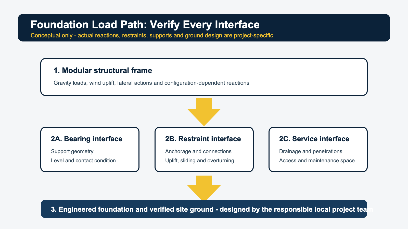
A modular building leaves the factory as a manufactured structural system, but its foundation is constructed in a geological, climatic and regulatory environment that the factory does not control.
That boundary is easy to underestimate.
A module may have clearly defined corner posts, longitudinal rails, transverse members or other bearing locations. Those features determine where the building is capable of transferring actions into its support system. The soil below the building, however, determines whether those reactions can be transferred into the ground without unacceptable settlement, movement or instability.
The foundation therefore has to solve two different problems simultaneously:
- match the structural support geometry of the modular system; and
- satisfy the site-specific geotechnical, environmental and regulatory conditions.
Published guidance from the Steel Construction Institute describes several foundation forms used with modular construction, including strip, trench-fill, pad and piled foundations, as well as rafts and ground beams. The same guidance stresses that foundation or ground-beam levelling is important to subsequent module alignment and notes that interfaces outside the modular manufacturer’s control require coordinated design responsibility.
In England, Approved Document A likewise treats foundations as part of the structural system alongside building loading and other structural elements. That document is jurisdiction-specific and should not be treated as a global design standard, but it illustrates the broader principle: the foundation cannot be separated from the building’s structural design basis.
For project owners and EPC teams, this changes the procurement question. Instead of asking the modular supplier for a generic “foundation drawing” and assuming it can be constructed anywhere, the project should establish a controlled information exchange between the manufacturer, engineering team and civil contractor.
What KUBO Site Evidence Shows About the Foundation Interface
KUBO’s first-party installation evidence illustrates why different projects can legitimately use different support concepts.
One industrial training-site photograph shows modular base frames positioned on prepared raised concrete support lines. The relevant observation is not that this is the “correct” foundation for every similar module. It is that the civil works have to correspond to the actual bearing geometry of the modular frame.
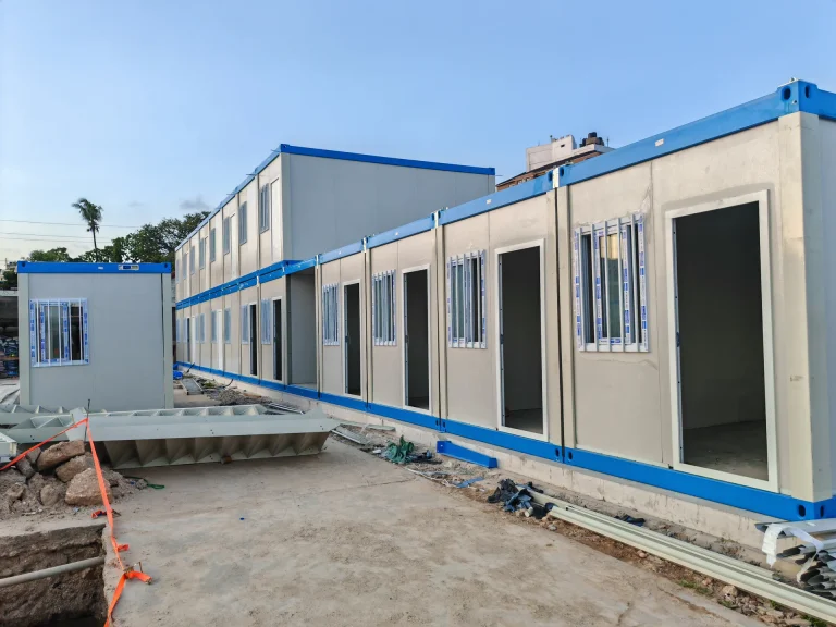
A separate training-facility installation photograph shows a long modular assembly erected along a continuous raised concrete base or slab edge. This makes several interface issues visible at once: bearing lines must be coordinated, the civil works must be set out before the modules arrive, level conditions affect installation, and delivery and erection access must be considered as part of site readiness.
Another KUBO photograph shows hillside accommodation elevated on steel piers. That image demonstrates a project-specific response to site conditions; it does not establish the capacity, permanence or universal suitability of elevated steel supports.
KUBO also uses internal foundation-layout information for different module formats. Those drawings map the actual support points to the released module base-frame geometry rather than assuming that every nominally container-shaped building can be supported on the same generic outline. Dimensions and project details remain system-specific and should be controlled through the project drawing process.
This leads to a useful manufacturer-side rule:
The civil foundation should be coordinated to the released module geometry; the module should not be forced to fit a foundation that was designed from assumptions about a generic container footprint.
Buyers comparing modular systems can review KUBO’s modular building system categories to understand why different structural systems may also create different installation and interface requirements.
What Determines the Right Prefab Building Foundation?
Several variables interact. Looking at only building weight or expected duration can produce the wrong conclusion.
Ground conditions and settlement behaviour
Foundation selection begins with the site, not with the catalogue.
The local geotechnical engineer may need to consider soil type, variability across the building footprint, fill material, weak strata, collapsible or expansive soils, groundwater, slope conditions and the possibility of total or differential settlement.
Differential movement is particularly important for modular construction because several factory-made units may have to align accurately with each other. Doors, wall joints, roof interfaces, stairs, corridors, utility connections and module-to-module connections can all be affected if individual support locations move differently.
A support arrangement that appears economical because it uses fewer bearing locations may therefore become unattractive if those locations concentrate reactions onto variable ground.
Conversely, a more distributed support system is not automatically better. It can require more excavation, formwork, reinforcement, concrete, surveying and coordination with underground services.
The correct comparison is project-specific risk, not simply the quantity of concrete.
Frost, moisture, drainage and groundwater
Water changes foundation decisions in several ways.
Surface drainage should prevent water from accumulating around support locations or beneath the building where it could affect soil conditions, corrosion exposure or maintenance access. Groundwater can affect excavation, construction sequencing and geotechnical performance. In cold regions, frost-related ground movement may influence foundation depth, material selection and site preparation according to local requirements.
These issues cannot be solved by declaring a modular building “temporary.”
A building that remains on site for only part of a project can still experience seasonal weather, flooding, frost or erosion while it is in service.
Gravity loads are only part of the problem
The foundation must participate in the complete structural load path.
Depending on the project, the relevant actions can include:
- building self-weight;
- occupancy and operational loads;
- equipment and service loads;
- roof and environmental actions;
- wind uplift;
- horizontal wind effects;
- seismic actions;
- sliding;
- overturning;
- eccentric load transfer;
- temporary erection actions; and
- forces introduced through stairs, canopies, corridors, platforms or other connected works.
This is why a visible concrete pad beneath a module does not tell a buyer whether the complete foundation system is adequate. Bearing support and lateral or uplift restraint may involve different components and different verification requirements.
Building height and configuration change foundation behaviour
A small single-level project and a larger stacked modular building can use the same basic module family while creating very different foundation demands.
Building height changes wind response, lateral-force transfer and overturning effects. Continuous corridors, external stairs, cladding, canopies and service structures can introduce additional reactions or interfaces. Changes in module arrangement can alter which support points carry load.
SteelConstruction.info specifically notes that building height and cladding options can influence foundation design even where modular units themselves are relatively lightweight.
For procurement teams, the implication is straightforward: foundation information should be based on the released project configuration, not simply the individual module type.
Duration and relocation intent matter—but they do not determine the answer alone
Temporary, semi-permanent and relocatable buildings create different commercial priorities.
A short project may place greater value on rapid site reinstatement, limited excavation and removable support systems. A multi-year workforce camp may justify more substantial civil works because long-term alignment, drainage, walkways, utilities and maintenance become more important. A building intended to move repeatedly may benefit from an engineered relocatable foundation concept that can be dismantled with the modules.
None of those intentions overrides structural requirements.
UK Health and Safety Executive guidance provides a useful jurisdiction-specific example. It states that temporary structures must be designed, installed and maintained for foreseeable loads, and it identifies site welfare and office units within the broader temporary-works environment. It also emphasizes planning, management and competent design where required.
“Temporary” describes use duration. It is not a structural design category meaning “engineering optional.”
Modular Building Foundations Decision Matrix
The following matrix is conceptual. It helps project teams identify which questions should be investigated before detailed engineering; it does not replace geotechnical analysis, structural design or local approval.
| Foundation concept | Duration / lifecycle fit | Ground variability | Load distribution | Utility coordination | Relocation intent | Site disturbance | Inspection / verification | Schedule and local-labor considerations | Interface risk |
| Isolated pads or piers | Can suit temporary through longer-duration projects when the structural system is designed around discrete support locations | Individual supports can become sensitive to variable soil or differential movement; site engineering determines suitability | Concentrates reactions at defined locations | Can leave useful access beneath parts of the building, but service penetrations and routes still require coordination | Removal may be simpler than more continuous concrete works in some projects | Potentially more localized than continuous foundations | Requires verification of each bearing location, set-out, elevation, stability and connections | May reduce continuous excavation, but accuracy across many individual supports can increase survey and workmanship dependence | High if generic pad locations are used instead of the manufacturer’s released support geometry |
| Strip footings or ground beams | Often considered where modules require coordinated bearing lines or where multiple units form long blocks | Can bridge or distribute support differently from isolated points, but still depends on geotechnical conditions | Can provide continuous or near-continuous bearing along defined module lines | Underground services must be planned around continuous foundation elements | Usually less convenient to remove than discrete relocatable supports | More continuous excavation and civil work may be required | Bearing line, level, straightness, connections and service crossings require controlled inspection | Can provide predictable module alignment when executed accurately; civil scope and local-labor input may be greater | Reduced only when the beam geometry, module geometry and civil set-out are coordinated |
| Slab or raft-type support | Can suit projects where the foundation, ground floor, circulation or service strategy favours a broad continuous civil platform | Can distribute actions across a larger area, but geotechnical design remains essential | Broad load distribution can be advantageous in some ground conditions | Can integrate or constrain utility routes depending on when sleeves, pits and penetrations are frozen | Usually not selected primarily for easy relocation | Greater permanent site intervention is possible | Requires control of overall levels, bearing areas, penetrations, embedded items, drainage and interfaces | Potentially more upfront civil coordination; can simplify some later site operations if correctly integrated | Interface risk shifts toward embedded services, level control and exact locations of module connections |
| Deep or piled foundation with ground beams / caps where required | Project-specific option where near-surface support is unsuitable or settlement and other geotechnical issues govern | Specifically investigated where deeper competent strata or other geotechnical conditions justify it | Transfers foundation actions through engineered deep elements | Requires early coordination because pile locations, caps, beams and services can conflict | Generally weak fit where minimal intervention and easy site restoration are dominant goals | Can involve significant specialist site operations | Specialist installation records, positioning and engineering verification are important | Greater specialist contractor dependency; procurement and site investigation become more significant | High if module reactions are frozen late or pile/cap geometry is developed before the modular structural scheme |
| Engineered relocatable supports | Particularly relevant where removal, reuse or repeated deployment is a genuine project requirement | Suitability depends strongly on ground conditions and the tested or engineered behaviour of the selected support system | May transfer loads through discrete points or another proprietary arrangement | Can preserve access for some service routes, but utilities still need independent planning | Relocation is a primary design objective | Can reduce irreversible civil works in appropriate applications | Support system capacity, stability, connections, ground preparation and installation condition require verification | May reduce some wet trades but can increase dependence on proprietary equipment, specialist installation or site preparation | High if “relocatable” is treated as permission to ignore uplift, sliding, settlement or local approval |
No row is a universal ranking. The same project can also use combinations—for example, a ground-beam system supporting modules while separate engineered foundations support stairs, canopies or external equipment.
Isolated Concrete Pads and Piers
Concrete pads are often attractive in early modular-project discussions because they appear simple. If the module has discrete structural support points, an isolated foundation concept may limit excavation and keep portions of the underside accessible.
The risks arise when simplicity becomes assumption.
A generic container house foundation drawing may show supports at corners because that is visually intuitive. The actual modular system may require other bearing locations, more continuous support, different reaction paths or specific connection details. Modules within the same project may also carry different loads because of stairs, wet rooms, internal openings, stacking or equipment.
Individual pads create another coordination challenge: level error or settlement at one support can affect the geometry of the entire module or block.
This is why the release information should identify the manufacturer-side support geometry before the local foundation engineer finalizes the site design.
Strip Footings and Ground Beams
Strip or ground-beam support becomes useful when the building needs coordinated bearing along defined lines rather than only at isolated points.
SteelConstruction.info notes that strips, rafts and ground beams can support modular units continuously around appropriate perimeters and highlights foundation levelling as crucial for module installation and alignment.
For a long accommodation block, site office or training building, the practical benefit can be easier coordination of repeated bearing lines—provided those lines were set out from the correct released module geometry.
The civil implications should not be overlooked. Continuous foundations can intersect drainage, water, sewer, electrical routes and other underground infrastructure. Excavation sequencing, backfilling, service crossings and access for module erection may become part of the foundation programme.
The correct design therefore considers the whole installation zone rather than treating the strip footing as an isolated concrete item.
Slabs and Rafts
A slab or raft can play several roles simultaneously: structural foundation, working platform, circulation surface, part of the ground-floor strategy or support for site operations surrounding the building.
This can create integration advantages where the project already needs substantial finished ground works.
It can also lock decisions in early.
Drainage points, utility penetrations, anchorage zones, level changes and the exact relationship between the module frame and the slab need to be coordinated before construction. Correcting a buried service or embedded connection after the slab is complete can be much more disruptive than revising a drawing before concrete is placed.
A slab should therefore not be selected simply because a project is described as “permanent.” The geotechnical engineer and structural designer still need to establish whether that foundation behaviour is appropriate for the actual site and building.
Deep and Piled Foundations
Deep foundations are a different category of decision.
They are not normally selected because the building is modular. They become relevant because site conditions, settlement criteria, structural actions or other geotechnical constraints require load transfer beyond the near-surface soils.
A modular project does, however, create an important coordination issue: pile, cap and ground-beam design needs the correct module reactions and support geometry early enough to avoid a civil structure that no longer aligns with the manufactured building.
This is one reason the foundation interface should be treated as a controlled design deliverable rather than a late site detail.
Engineered Relocatable Modular Foundation Options
A relocatable modular foundation is most valuable when relocation is part of the actual asset strategy rather than a marketing description.
Possible concepts can involve engineered steel supports, proprietary adjustable systems, removable piers or other support assemblies. The appropriate type depends on the structural system, soil, environmental actions, stability requirements, corrosion exposure and local rules.
The commercial advantage is potentially significant: less irreversible construction may make demobilization and site reinstatement easier.
The engineering obligation remains.
As one jurisdictional example, the City of Portland’s guidance for prefabricated structures addresses geotechnical requirements, structural support, positive mechanical connections and engineering-based verification of certain foundation or anchorage systems. Those Portland provisions are not universal rules and their numerical requirements should not be transferred to other projects, but the underlying lesson is useful: alternative or removable supports still sit inside a formal engineering and approval framework.
A buyer considering relocatable supports should therefore ask two separate questions:
Can the support system be removed?
and
Has the complete support, restraint and ground interface been engineered for this project?
Only the second question establishes technical suitability.
Foundation Responsibility Matrix
Foundation problems frequently originate not in calculation but in scope ambiguity. The following responsibility matrix provides a clearer project boundary.
| Party | Typical foundation-interface responsibility | Information it should receive | What it should not assume |
| Modular manufacturer | Define released base-frame geometry, intended bearing locations, module-side connection information, applicable structural inputs or reactions, installation interfaces and changes affecting the foundation | Final project configuration, destination engineering requirements and questions from the local design team | That a generic foundation detail is suitable for unknown soil, wind, frost, seismic or approval conditions |
| Buyer / EPC contractor | Establish scope boundaries, appoint competent local engineering resources, coordinate programme, ensure module and civil information are exchanged, control change management | Manufacturer drawings, site investigation, civil design status, authority requirements, logistics and installation plan | That either the manufacturer or civil contractor automatically owns every interface not written into the contract |
| Local geotechnical / structural engineer | Interpret site investigation; establish foundation behaviour; design for ground, structural actions and local code; determine site-specific support and restraint requirements | Released module data, actual layout, building use/configuration, environmental design inputs and site information | That the nominal external dimensions of a module define its structural load path |
| Civil / site contractor | Construct the designed foundation, manage excavation and site preparation, control embedded items and drainage, record inspections and survey completed works | Approved-for-construction civil drawings, specifications, hold points and module interface information | That deviations in level, position or bearing condition can be corrected by the installation crew without engineering review |
| Module installation team | Verify agreed readiness conditions before erection, install modules and designated connections according to released information, identify clashes or deviations | Site-release records, module drawings, lifting/installation method, foundation survey and connection details | That erection should proceed because modules and crane have already arrived |
| Local authority / approving body | Apply the destination’s permitting, structural, geotechnical, temporary-building or other regulatory requirements as applicable | Required design submissions and professional documentation | That factory manufacture or temporary use removes local approval obligations |
This separation is consistent with modular-construction guidance noting that interfaces beyond the manufacturer’s direct control require design coordination elsewhere in the project team.
Foundation-Interface Release Workflow
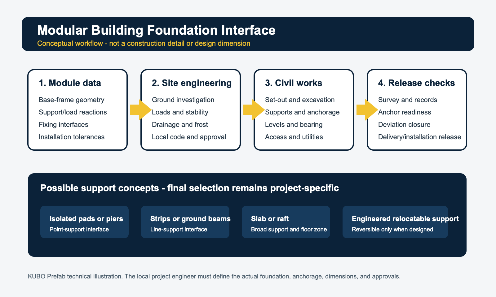
A disciplined foundation process can be represented as four broad stages—module data, site engineering, civil works and release checks—but each stage contains specific decisions.
1. Freeze the relevant module configuration
The foundation engineer needs the configuration that will actually be constructed.
That includes the selected structural system, module arrangement, stacking or building height where applicable, major openings, stairs or attached structures, significant equipment and any changes that affect support reactions.
Foundation engineering performed against an outdated module revision creates avoidable rework.
2. Complete the necessary site investigation
The local engineering team establishes the information required for geotechnical design.
The appropriate investigation depends on the jurisdiction, project scale, ground conditions and foundation concept. It should not be replaced by photographs or assumptions that the ground “looks hard.”
3. Exchange manufacturer interface data
The manufacturer releases the support geometry and agreed structural information needed by the local engineer.
The key control is revision status. A preliminary module drawing should not silently become the construction basis for permanent civil works.
4. Develop the local foundation design
The local engineering team combines module requirements with soil, groundwater, frost, drainage, environmental actions, local codes, utilities and site constraints.
This is where a conceptual preference—pads, strips, raft, piles or relocatable supports—becomes an engineered project solution.
5. Coordinate services, access and external works
Foundation drawings should be checked against more than the module plan.
Underground drainage, potable water, wastewater, power, data, earthing, access roads, crane setup, walkways, stairs and other site structures can all conflict with foundation elements.
6. Construct and inspect the civil works
The site contractor executes the approved design while maintaining the required inspection and record system.
Changes encountered in the field should be documented rather than solved informally where they affect structural or installation interfaces.
7. Survey the completed foundation and close deviations
A completed foundation should be checked against the information required for module installation.
Where set-out, elevation, connection locations, bearing surfaces or other controlled characteristics deviate from the accepted design, the responsible engineering parties determine the disposition.
The installation team should not be expected to redesign the civil works during unloading.
8. Release the site for module delivery and erection
Module delivery is a logistics event; foundation release is an engineering and construction-control event.
Connecting the two improves schedule certainty. If modules arrive before unresolved civil deviations are closed, the project can incur crane standby, temporary storage, repeated handling, unsafe improvisation or installation delays.
Site-Readiness Hold Points Before Module Delivery
| Hold point | What should be confirmed | Why it matters | Typical consequence if unresolved |
| Set-out | Support lines, bearing locations and connection positions correspond to the released project drawings | Modular geometry depends on accurate alignment between factory and civil works | Modules may not land on intended structural supports or may require engineering rework |
| Level and elevation | Completed bearing elevations have been surveyed and accepted under the project requirements | Level foundations support module alignment, connections, doors, envelope interfaces and multi-module fit-up | Installation difficulty, accumulated misalignment or corrective site works |
| Bearing surfaces | Surfaces intended to receive the building are complete, sound and free of conditions that prevent the designed contact | The structural load path begins at the physical module-to-foundation interface | Concentrated bearing, unintended gaps or unstable erection conditions |
| Drainage | Finished grades and temporary/permanent drainage arrangements do not direct water toward vulnerable foundation zones | Water can affect ground conditions, access, corrosion exposure and maintenance | Ponding, erosion, construction disruption or later maintenance problems |
| Anchorage / restraint interface | Designed connection points, embedded items or other restraint provisions are complete and accessible | Gravity support alone may not satisfy uplift and lateral requirements | Installation stops or unsafe improvised connections |
| Access and crane setup | Delivery route, unloading areas, lifting positions and any required working platforms are available | A technically complete foundation can still be unusable if modules cannot be safely delivered and erected | Rehandling, crane repositioning, delayed installation or temporary works changes |
| Utility interfaces | Underground services, penetrations and connection points are in the coordinated locations and protected from installation damage | Modular service connections often depend on accurate site interfaces | Excavation after erection, inaccessible connections or service conflicts |
| Inspection and survey records | Required civil inspections, surveys and approvals are complete and available | Installation teams need a defined basis for accepting site readiness | Disputes over whether a visible condition is within the approved design |
| Unresolved deviations | All structural or interface deviations have an approved disposition before erection | Field crews should not make engineering decisions under delivery pressure | Schedule loss, unsafe workaround or hidden nonconformance |
This hold-point approach also addresses a practical reality of modular construction: factory manufacturing and site civil works often proceed in parallel. Parallel work can shorten the overall programme, but only if both streams converge on the same controlled interface information.
Common Foundation Interface Failures
Designing from a nominal module outline
The most basic error is treating the external rectangle of a modular unit as its structural bearing plan.
Two buildings with similar external dimensions can have different frame arrangements, support requirements and connection systems.
The civil engineer should work from manufacturer-released structural interface information, not from an architectural outline alone.
Freezing civil works before the modular configuration
Procurement teams sometimes want to start foundations early to protect the site schedule.
That can be sensible—but only when the module data needed for foundation design is genuinely frozen.
If building length, stacking, structural openings, stairs, service cores or module type continue changing after concrete construction starts, the supposed schedule gain can become rework.
Treating level problems as an installation problem
SteelConstruction.info emphasizes the importance of foundation levelling for modular installation and alignment.
A site team should therefore distinguish between planned adjustment within an engineered installation system and attempts to compensate for uncontrolled civil deviations.
The latter can alter bearing behaviour, connection geometry and envelope alignment.
Ignoring uplift and lateral restraint
A module can be heavy enough to appear stable under gravity while still requiring engineered resistance to wind uplift, sliding, overturning or seismic effects.
Visible mass is not a substitute for structural analysis.
This becomes especially important with exposed mining sites, wind-energy projects, coastal projects and elevated support conditions, although the governing environmental inputs remain location-specific.
Treating drainage as separate from foundations
Poor water management can undermine an otherwise appropriate foundation concept.
Drainage should be coordinated with ground preparation, finished level, access areas, roof discharge, surface-water routes and erosion control. Where modules are elevated, the space beneath the building may also require deliberate drainage and maintenance planning.
Assuming relocation means no civil engineering
The project may successfully remove every steel support at demobilization and still have experienced an unsafe foundation if those supports were never engineered for the ground and structural actions.
Relocatability is a lifecycle characteristic. It does not eliminate foundation mechanics.
Temporary, Semi-Permanent or Relocatable: How Should the Early Decision Change?
Temporary project buildings
For short-duration project offices, welfare facilities or accommodation, buyers commonly value:
- limited site disturbance;
- fast civil preparation;
- straightforward removal;
- accessible utilities;
- predictable installation; and
- reasonable reinstatement requirements.
Those priorities may favour discrete or removable support concepts, but local engineering still determines feasibility.
The project should also consider whether “temporary” status has a specific definition under the destination’s planning, building or temporary-works regime.
Semi-permanent project accommodation
A multi-year camp often changes the lifecycle balance.
Drainage, settlement control, external walkways, utility networks, maintenance access and repeated seasonal exposure become more influential. Investing more heavily in civil infrastructure may be rational even if the modules themselves remain relocatable.
The foundation should reflect the operational period rather than an assumed distinction between “temporary module” and “permanent concrete.”
Buildings intended for repeated relocation
Here the support strategy becomes part of asset planning.
A buyer may accept greater upfront engineering or proprietary-support cost if that system avoids demolition and reconstruction during future deployment cycles.
To evaluate the business case properly, procurement teams should include:
- support-system transport;
- inspection between deployments;
- replaceable components;
- compatibility with different soil conditions;
- required site preparation;
- anchorage or restraint;
- storage;
- engineering for each new destination; and
- local approval.
A relocatable building does not imply that the same foundation solution can be reused unchanged at every future site.
How Foundation Choice Affects Project Risk Beyond Concrete Cost
A useful foundation comparison should include more than the civil contractor’s quotation.
Schedule certainty
A simple support concept with unclear module geometry can be riskier than a more substantial foundation with fully coordinated drawings.
Schedule certainty depends on information release, design approval, materials, local contractor capability, weather, inspection, survey and closure of deviations.
Local-labor dependency
Concrete-intensive foundations can increase dependence on excavation, reinforcement, formwork, concrete supply and local finishing quality.
Proprietary relocatable systems may reduce some wet trades but increase dependence on specialist equipment or trained installers.
Neither is automatically more reliable. The project needs to match the support concept to the resources actually available at the destination.
Logistics
Foundation readiness controls the delivery sequence.
If modules cannot be erected immediately, temporary storage and repeated lifting may be required. On remote mining or infrastructure projects, that can create operational consequences far beyond foundation construction itself.
Scalability
A support concept that is straightforward for a few modules may become difficult to survey and control when repeated across a large accommodation block.
Conversely, investing in repeated ground beams or a coordinated slab may become more rational as a development grows.
The scale of the complete building—not just the support detail for one module—should therefore be part of early assessment.
Maintenance
Accessible supports can simplify inspection of some connections and utilities. Enclosed or ground-level arrangements may better suit other operational requirements.
Corrosion, drainage, vegetation, erosion, frost movement and settlement observations may all become part of the maintenance strategy depending on the selected system.
Approval risk
Non-conventional does not mean unacceptable, but unfamiliar support systems can require more engineering documentation or authority review.
Portland’s prefabricated-structure guidance is a useful example: the city’s approach explicitly connects foundation options with geotechnical information, structural verification and positive mechanical connections. Again, its specific rules apply locally, but it demonstrates why approval strategy should be considered while selecting the foundation concept rather than after procurement.
What Information Should a Buyer Prepare Before Foundation Coordination?
A TOFU-stage project does not need a finished foundation design before speaking with a modular supplier. It does need enough information to identify the correct interface questions.
Prepare, where available:
- project location;
- intended building use;
- modular system being considered;
- preliminary building layout;
- number of levels or stacking concept;
- approximate project duration;
- whether the building will be relocated;
- available site or geotechnical information;
- frost, groundwater or flooding concerns;
- governing structural and building-code basis;
- project wind, snow and seismic information where already established by the engineering team;
- utility routes and connection strategy;
- expected external stairs, walkways, canopies or attached structures;
- site grading and drainage concept;
- crane and delivery access constraints;
- local civil-contractor capability; and
- authority or permit requirements already identified.
The manufacturer can then define the building-side information needed for the local engineers to progress.
Review the Site Foundation Interface Before Civil Works Are Frozen
The safest early decision is not to select a concrete detail from a catalogue. It is to establish a clear interface between the modular system and the site foundation.
Before foundation construction begins, the project team should know:
- which module revision governs;
- where the structural support locations actually are;
- which party supplies foundation reactions or other required design inputs;
- who owns geotechnical and local structural engineering;
- which foundation concept is being evaluated;
- how uplift and lateral restraint are addressed;
- where utilities and drainage cross the civil works;
- what must be surveyed before installation; and
- who has authority to release the site for module delivery.
If you are evaluating KUBO systems for a project, review the available modular building system categories first, then review the site foundation interface with the project team. Useful inputs include the building configuration, site location, intended duration, relocation requirement, available ground information, environmental design basis, preliminary utilities and local engineering requirements.
The objective is not for the factory to replace the local foundation engineer. It is to make sure the engineer receives the correct module-side information before the civil design is frozen.
Frequently Asked Questions About Modular Building Foundations
1. What is the best foundation for a modular building?
There is no universal best foundation. Pads or piers, strip footings, ground beams, slabs or rafts, deep foundations and engineered relocatable supports can all be appropriate in different projects.
The decision depends on the module’s actual load-transfer geometry, soil conditions, settlement behaviour, frost, groundwater, drainage, wind and seismic actions, building configuration, utilities, duration, relocation plans and local approval requirements. A conceptual choice becomes a usable foundation only after project-specific engineering.
2. Can modular buildings be installed on concrete pads?
Yes, some modular systems can use isolated concrete pads or piers where discrete support locations are compatible with the building’s structural design and the local foundation engineer confirms the site solution.
The important issue is not merely whether concrete pads are present. Their locations must correspond to the released module support geometry, and the complete foundation system must address the required gravity, uplift, lateral, settlement and local-code conditions.
3. When are strip footings or ground beams useful for modular buildings?
Strip footings and ground beams can be useful where the modular system benefits from continuous or coordinated bearing lines, particularly across repeated module arrangements.
They may also assist alignment, but they introduce civil coordination around excavation, services, drainage and access. SteelConstruction.info specifically identifies strip foundations and ground beams among established modular-building foundation interfaces and notes the importance of accurate levelling.
4. Does a temporary modular building need an engineered foundation?
Temporary use does not automatically remove engineering requirements.
The structure still has to remain stable under the actions that can occur during its intended use. Requirements vary by jurisdiction, but UK HSE guidance, for example, states that temporary structures must be designed, installed and maintained for foreseeable loads and that temporary works require planning and management.
The destination engineer and relevant authority should determine the applicable project requirements.
5. Can a relocatable modular building use removable foundations?
Potentially. Engineered removable piers, steel support systems and other relocatable concepts may support a project strategy that prioritizes demobilization and site restoration.
Their removability does not demonstrate structural adequacy. Ground bearing, settlement, uplift, sliding, overturning, connection behaviour, corrosion, drainage and local approval still need to be addressed for each deployment site.
6. Is a container house foundation the same as a shipping-container foundation?
It should not be assumed so.
“Container house” is used commercially for several modular building systems whose structural frames, support points and load paths may differ from an ISO freight container and from one another. A foundation should therefore follow the structural information for the actual manufactured building rather than a generic container outline.
7. Who should design the prefab building foundation?
The local geotechnical and structural engineering team normally needs to finalize the site foundation because it is responsible for the actual ground conditions, destination loads and applicable regulations.
The modular manufacturer should provide the module-side interface information required for that work. The buyer or EPC contractor should make the boundary explicit so that neither side assumes the other owns missing design information.
8. Why is foundation level so important for modular construction?
Modular construction relies on factory-made units fitting together on site. Errors in foundation level can therefore affect module alignment, connections, doors, wall and roof interfaces, corridors, stairs and services.
SteelConstruction.info specifically describes foundation or ground-beam levelling as crucial to subsequent modular installation and alignment.
The applicable project tolerances should come from the coordinated engineering and manufacturer information rather than a generic value.
9. Can the modular manufacturer provide a standard foundation drawing?
A manufacturer can provide system-specific interface drawings or conceptual foundation information, but a generic drawing should not be mistaken for a finished site foundation design.
The site foundation must still respond to ground conditions, environmental actions, groundwater, frost, drainage, utilities, building configuration and local codes. Where KUBO foundation-layout information is used, its purpose is to communicate the module’s actual support geometry to the responsible site engineering team.
10. What should be checked before modules are delivered to the foundation?
At minimum, the project should confirm that the foundation has been constructed from the current approved design and that agreed site-readiness checks are closed.
Important interfaces include set-out, bearing locations, level, bearing surfaces, anchorage or restraint provisions, drainage, underground services, installation access, crane setup and unresolved construction deviations. Survey and inspection records should be available to the party responsible for releasing the site.
Delivering modules before these issues are closed can convert a civil discrepancy into a logistics and installation problem.
Sources and References
- GOV.UK — Structure: Approved Document A — England-specific structural guidance covering building loading and structural elements including foundations.
- Steel Construction Institute / SteelConstruction.info — Modular Construction — technical guidance describing modular foundation interfaces including strip, pad, piled, raft and ground-beam concepts, foundation levelling and design-coordination responsibilities.
- City of Portland — Building Code Guide 15-10: Prefabricated Structure Foundations — jurisdiction-specific example of geotechnical review, structural support, anchorage and engineering requirements for prefabricated structures.
- UK Health and Safety Executive — Temporary Works Guidance — UK-specific guidance on planning, designing, installing, maintaining and inspecting temporary structures and support arrangements.