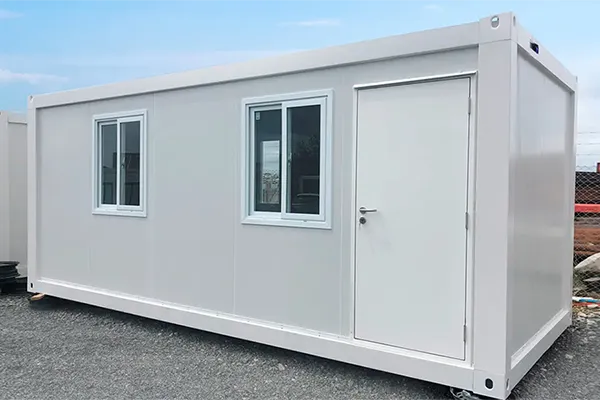


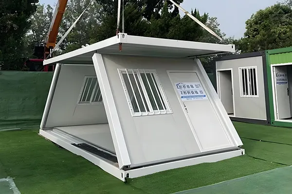

Summary
Good modular building waterproofing is not created by a single sealant, membrane, roof panel, gutter or factory inspection. Water-intrusion risk is controlled by a continuous system: the roof must collect water, maintain an effective drainage path under real loading and tolerances, move water toward outlets, transfer it through gutters or channels, discharge it through a controlled route, and keep joints, penetrations and transitions sealed throughout transport, assembly and operation.
For buyers, the most useful question is therefore not, “Is this modular building waterproof?” It is: “Can the supplier and project team show me exactly where rainwater goes from the moment it lands on the roof until it is safely discharged away from the building?”
That distinction matters. U.S. EPA moisture-control guidance treats roofs, walls, plumbing, site drainage, construction practices and maintenance as parts of the same moisture-management problem rather than isolated products. England’s Approved Document H similarly frames roof drainage as a route from the roof toward an appropriate outfall while addressing blockage, leakage, access for clearing and safe overflow behavior.
For prefabricated and modular buildings, another layer of risk must be considered: some critical interfaces are completed in a factory, while others are exposed to packing, transport, temporary storage, lifting and site assembly. A roof detail that is sound in a drawing can still become vulnerable if modules are misaligned, seal surfaces are contaminated, penetrations are added later, drainage outlets are obstructed, or final discharge arrangements are not coordinated with site civil works.
The practical conclusion is simple: buyers should review the complete roof water path, critical waterproofing interfaces, responsibility boundaries and post-assembly inspection plan before treating a modular roof package as complete.
Why Modular Building Water Leakage Is Usually a System Problem
When water appears inside a modular building, the visible wet spot is not necessarily where the failure began.
Rain may enter through a roof-panel joint, a fastener penetration, flashing around equipment, an incomplete module-to-module interface or a sealant termination. It can then travel along a steel member, insulation layer, ceiling panel or service route before becoming visible elsewhere.
The reverse can also happen: an apparently sound roof covering may be subjected to conditions it was never intended to manage because drainage is ineffective. A blocked outlet, local low point or incorrect discharge path can keep water against joints for longer periods, increase the amount of water reaching small imperfections, or direct runoff toward walls and openings.
This is why prefab roof drainage and waterproofing should be reviewed together.
Drainage manages how much water reaches an interface and how long it remains there. Waterproofing manages the interfaces that water cannot simply avoid. Structural behavior affects both because roof geometry under service conditions determines where water actually travels. Site works matter because the water still needs somewhere safe to go after leaving the building.
The U.S. General Services Administration’s P100 standards apply specifically to GSA-owned buildings, so they should not be treated as a universal modular-building code. They are nevertheless useful as an engineering example because the standards emphasize positive drainage, avoidance of trapped water and drainage redundancy where blockage could create ponding risk.
That is a better way to think about container house roof waterproofing as well. Rather than searching for one supposedly waterproof component, buyers should verify whether the complete assembly manages predictable failure paths.
The Roof Water-Path Verification Map Buyers Should Request
A useful roof review begins with the catchment area and ends outside the building.
If any section of that route is unclear on the drawings, it represents an interface that still needs to be resolved.
Catchment Surface: Where Does the Rain Actually Land?
The starting point is the roof geometry itself.
A buyer should be able to identify which roof surfaces drain toward which edges, channels, gutters or outlets. This sounds elementary, but modular arrangements can complicate the answer. A single module may behave differently after several units are connected into a larger block. Parapets, roof upstands, external walkways, canopies, equipment supports or adjoining roof sections can also change catchment behavior.
The design inputs should therefore include the actual roof area and shape, building configuration, rainfall criteria required by the destination, expected deflection, penetrations and the intended discharge route.
A nominal roof slope alone does not answer the question. Construction tolerances, structural movement and local deformation can alter the effective drainage surface. Buyers should ask how the specified geometry is preserved after manufacture and assembly and whether the drainage direction remains evident in the completed building.
No universal slope should be copied from another project. The appropriate arrangement depends on the roof system, rainfall design basis, structural behavior, local requirements and drainage configuration.
Fall and Deflection: Will the Finished Roof Still Drain?
Drawings usually represent ideal geometry. Installed buildings include tolerances.
For that reason, the review should distinguish between designed fall and effective drainage after fabrication, lifting, connection and loading.
Critical questions include whether roof members can create local depressions, whether connected modules remain level relative to one another, whether joints form unintended dams, and whether a roof designed to drain in one direction could develop a low point after installation.
This does not mean every roof needs a complex calculation solely for drainage. It means the drainage concept must be compatible with the structural system and installed geometry rather than existing only as an arrow on a schematic.
Where the project has unusual spans, additional rooftop items, substantial snow considerations or other structural demands, the local design team should evaluate those conditions within the governing engineering framework rather than relying on a generic factory detail.
Channel or Gutter: Can Water Reach the Outlet Without Being Trapped?
Some modular buildings use exposed gutters. Others integrate channels into roof-edge or frame details. Different systems may direct water through another controlled path.
None is automatically superior.
The buyer should instead inspect continuity. Is there a clear route from the roof surface into the channel? Are joints located where they could obstruct the flow? Could debris become trapped? Can the channel be inspected and cleaned? What happens at a module connection? Is the discharge path still continuous when units are joined into a larger building?
England’s Approved Document H provides a jurisdiction-specific example of this logic: its H3 guidance addresses carrying rainwater from the roof to an outfall, minimizing blockage and leakage, maintaining access for clearing, and laying gutters toward outlets. It also considers what happens when rainfall exceeds drainage capacity. These provisions apply in England and are not universal dimensions or sizing rules for exported modular buildings.
Outlet: Where Is the Most Restrictive Point?
An outlet can become the bottleneck even when the roof and gutter appear adequate.
Buyers should ask to see the outlet location, opening geometry, connection to the next drainage component and access for inspection. If an outlet is concealed within a frame or corner, the drawing should make that route understandable rather than leaving it implied.
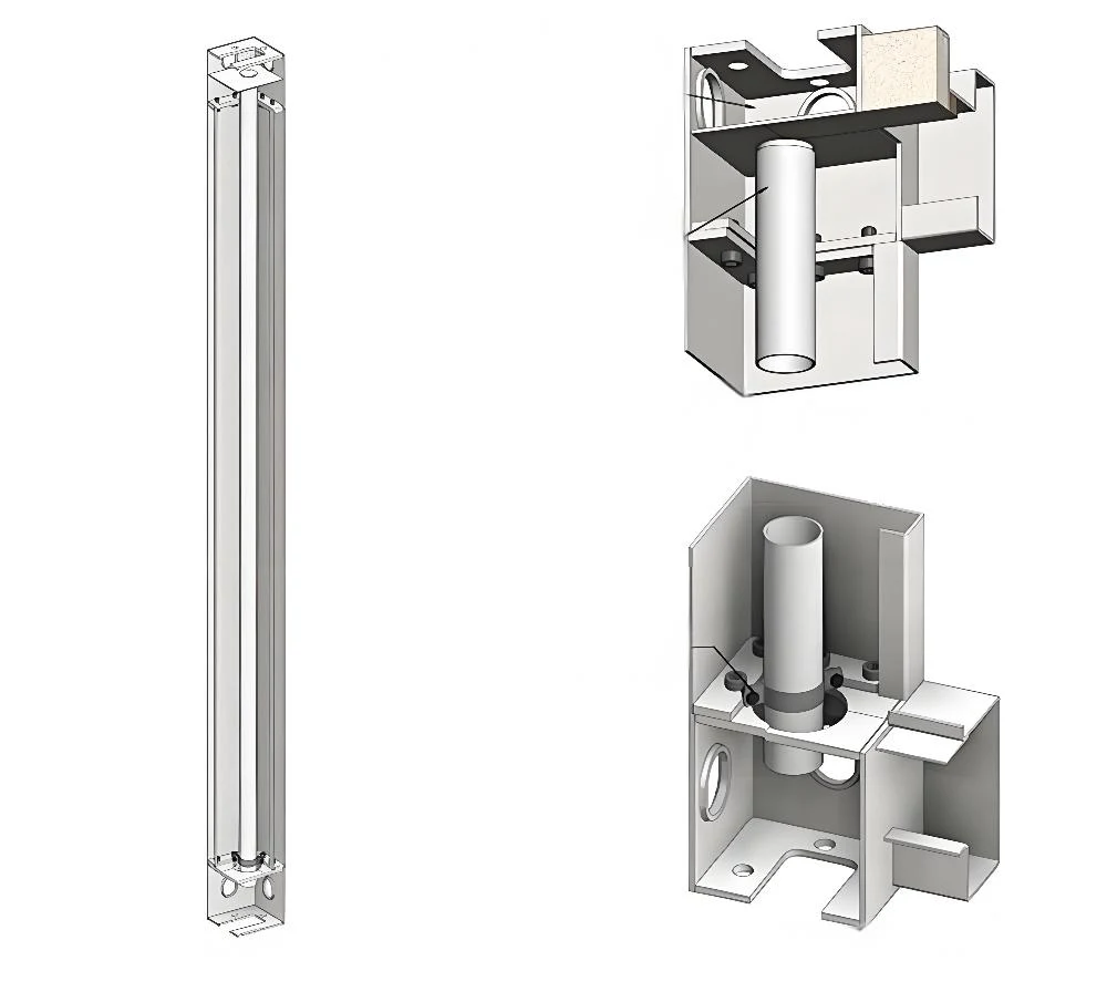
KUBO has an assembly illustration showing a vertical pipe routed within a modular corner or column. It is useful as an example of how a controlled drainage route can be integrated into a modular element, but it should not be interpreted as a universal KUBO drainage configuration or evidence of a particular drainage capacity.
The broader buyer lesson is more important: if water disappears into a concealed construction zone, the drawings should show where it goes next.
Downpipe or Controlled Vertical Route: What Happens at Connections?
The route from roof level to ground level introduces more interfaces.
A vertical pipe may have connections between components, movement interfaces, supports and transitions at the base. An external downpipe can be visually accessible but exposed to impact. An internal route may be protected but requires particularly clear inspection and maintenance provisions because leaks can be concealed.
The correct approach is project-specific.
Buyers should ask whether the vertical route is accessible where maintenance is expected, how connection points are sealed, how movement is accommodated where necessary, and what happens if the pipe becomes partially obstructed.
Discharge and Site Drainage: Where Does the Water Go After Leaving the Module?
The manufacturer’s roof drainage scope does not automatically solve site drainage.
Water discharged at the base of a building still needs a final route. If it is released against foundations, support pads, pedestrian routes or unprepared soil, a successful roof-drainage system can simply move the problem elsewhere.
Depending on the site, uncontrolled discharge may contribute to erosion, splash-back, standing water, access problems or unwanted water around foundations and utility areas.
KUBO’s current flat-pack product information explicitly separates factory-side building work from buyer and local responsibilities such as foundations, civil drainage and external utilities. This is an important procurement boundary: the module supplier can provide defined drainage interfaces, while the project team must coordinate those interfaces with the actual site.
Roof Water-Path Verification Map
| Water-path stage | What the buyer should be able to verify | Project variables that change the answer | Typical risk if unresolved |
|---|---|---|---|
| Catchment surface | Roof areas and the intended drainage direction are identifiable | Roof shape, connected modules, canopies, equipment, rainfall basis | Water is directed toward an unintended edge or joint |
| Fall and installed geometry | Effective fall remains after fabrication and assembly | Structural deflection, tolerances, support levels, loading | Local ponding or reverse fall |
| Channel or gutter | Continuous route to an outlet, with practical access | System type, module joints, debris exposure, roof configuration | Trapped water, overflow or difficult cleaning |
| Outlet | Location, transition and inspection access are shown | Catchment area, rainfall criteria, outlet arrangement | Local bottleneck or concealed blockage |
| Downpipe/vertical route | Pipe routing and connections are defined | Internal vs external routing, modular joints, impact exposure | Leakage at connections or inaccessible failure |
| Discharge | Water exits clear of sensitive building interfaces | Building elevation, support system, walkways, local grading | Splash-back or concentration at the building base |
| Site drainage | Final outfall is coordinated with civil works | Soil, grading, stormwater design, local requirements | Erosion, standing water or foundation-area saturation |
A buyer does not need to become the roof designer to use this map. The objective is to expose gaps between disciplines before those gaps become site problems.
Waterproofing Details That Should Be Visible Before Production
Drainage reduces exposure, but it cannot eliminate the need for a coherent waterproofing strategy.
The Modular Building Institute describes modular waterproofing as a coordinated system rather than a single product and notes that factory application can provide controlled conditions for some waterproofing work. The article also emphasizes that the approach needs to fit project and climatic conditions. As an industry source rather than a building code, it is useful for understanding modular-process considerations but should not replace project-specific engineering or local compliance review.
For buyers, this means drawings and inspection records should show the interfaces where continuity matters.
Roof Panel Joints
Panel joints deserve more scrutiny than the panel face itself.
The buyer should understand how adjacent roof elements overlap, engage, compress, fasten or seal; how water is prevented from being driven into the joint; and how a field-installed joint differs from one completed under factory conditions.
Where several modules connect, the module-to-module roof interface deserves particular attention. The assembly sequence should show when the joint is completed and what must be inspected before it is concealed.
A specification that merely lists “sandwich panel roof” or “waterproof roof” is not enough to answer these questions.
Sealant Interfaces
Sealant is useful, but it should not become a substitute for unresolved geometry.
The important issues are where sealant begins and ends, what surfaces it bonds to, whether those surfaces remain accessible and clean during assembly, and whether movement is expected across the joint.
The buyer should also know which seals are factory-installed and which require field application. Field-applied seals introduce workmanship and weather dependencies: dust, moisture, surface contamination and rushed sequencing can affect the finished interface even when the specified material is suitable.
Sealants also require future inspection. A joint that cannot be reached after handover deserves a different level of design scrutiny from one intended to remain serviceable.
No generic sealant life should be promised without reference to the actual material, joint design, exposure and maintenance conditions.
Fasteners and Mechanical Penetrations
Every penetration through a water-control layer deserves a clear detail.
That includes fasteners, brackets, anchors, roof-mounted equipment supports and any later additions introduced by other trades.
The critical question is not simply whether a fastener has a washer. It is whether the complete penetration detail maintains the intended water-shedding or waterproofing sequence after installation and movement.
Uncontrolled site modifications are particularly important. A building may leave the factory with a coherent roof package and later receive antennas, exhausts, cables, HVAC components or other equipment. Unless those penetrations are coordinated, the original roof inspection tells the buyer little about the final condition.
Corners, Upstands and Changes in Direction
Waterproofing systems are usually easier to understand on a broad flat surface than at transitions.
Corners, upstands, roof edges, parapets, changes in level and intersections between materials concentrate geometry and workmanship. These areas should be visible in detail drawings, not hidden behind a general note saying “seal all joints.”
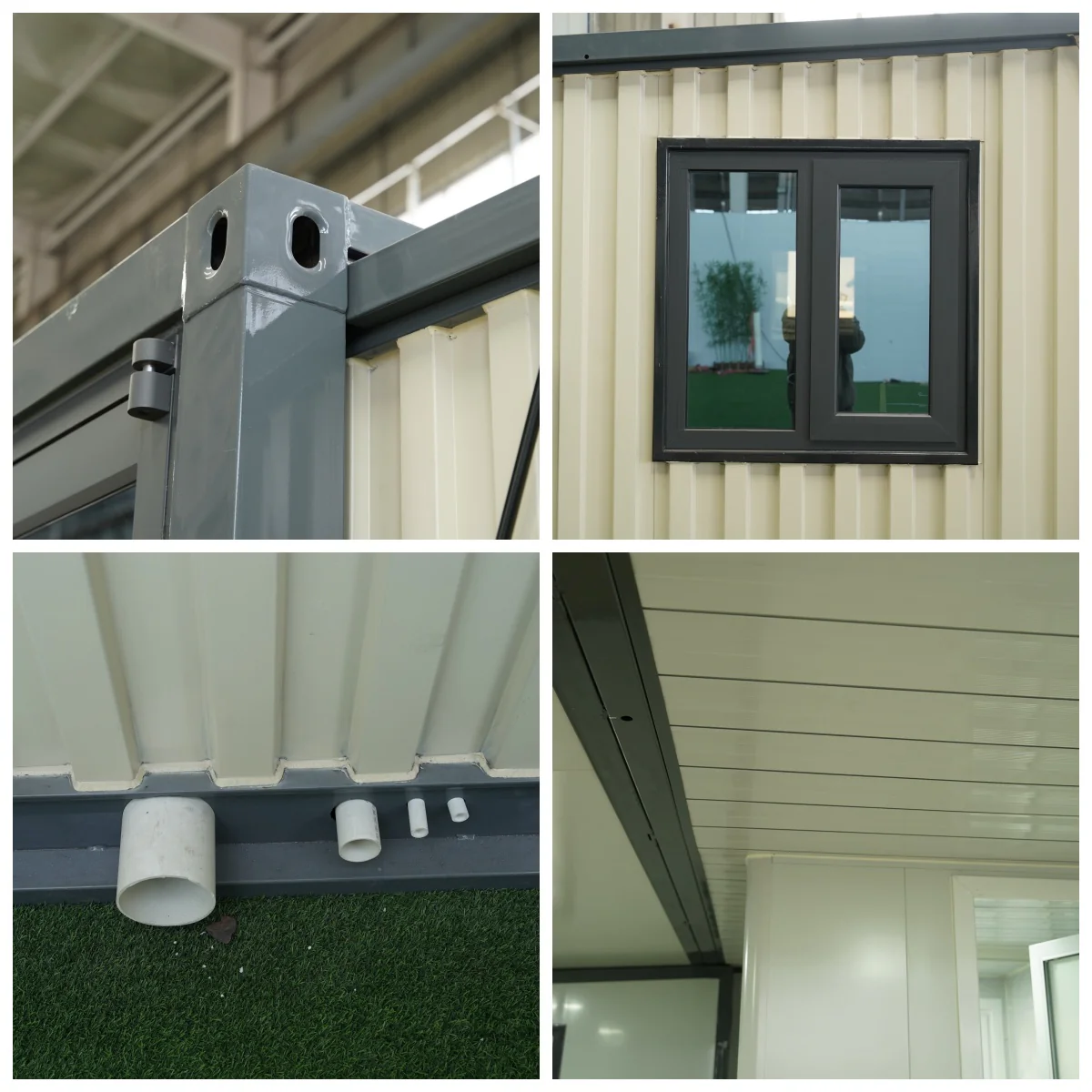
A KUBO detail collage supplied for this article includes module corner openings, wall/window interfaces, small outlets and an underside/ceiling junction. These images are useful because they direct attention toward interfaces that buyers can inspect. They do not provide test values or prove the performance of every KUBO configuration.
This is a useful standard for evaluating supplier imagery generally: detail photographs can demonstrate construction anatomy; they are not a substitute for project-specific drawings, inspections or tests.
Roof Penetrations and Service Interfaces
Penetrations deserve coordination before production whenever possible.
The project team should identify roof-mounted equipment, exhausts, vents, cable routes and other services early enough for the roof detail to be designed around them. Late changes are not automatically unacceptable, but they create a new waterproofing interface that should be reviewed and documented.
The same principle applies to penetrations near drainage paths. An obstruction can alter local flow, trap debris or create a low point even if its own flashing is sound.
Why Modular Construction Changes the Waterproofing Inspection Sequence
A conventionally built roof is assembled largely in its final location. A modular roof may pass through several conditions before occupancy.
KUBO’s flat-pack system, for example, is described as pre-manufactured floor, roof, wall and frame components that are packed for transport and assembled at the destination. Its published workflow separates approved drawings, material schedules, factory inspection, packing sequence, assembly guidance and final site interfaces.
That means the buyer should think about waterproofing at more than one release point.
Factory Completion Does Not Equal Final Installed Condition
Some joints, coatings, panels or drainage components may be completed or checked at the factory. Others cannot reach their final condition until modules are connected on site.
A factory inspection should therefore answer, “Is this component ready for shipment?” A post-assembly inspection answers a different question: “Does the completed building have the intended continuous water-management system?”
Confusing these two releases creates a documentation gap.
Transport Can Affect Interfaces Without Obvious Structural Damage
Transport damage is not limited to dramatic dents.
Edges can be scratched. Protective components can shift. Seal surfaces can become contaminated. Bundled components can rub. Small fittings can be lost or damaged during unpacking. A roof piece that remains structurally usable may still require interface repair before installation.
This is why receiving inspection should include critical roof and drainage components rather than only package counts.
Temporary Site Exposure Matters
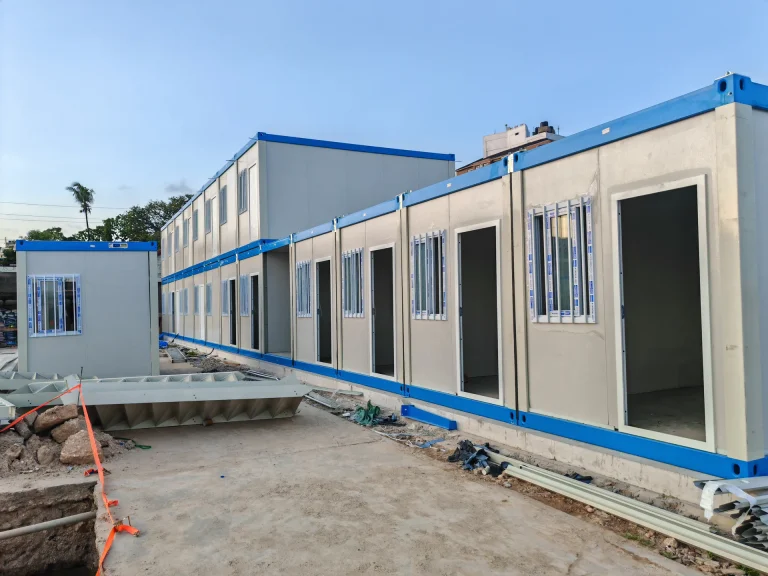
KUBO Media ID 2886 shows modular camp buildings during phased roof installation near wind turbines. It demonstrates something valuable for procurement teams: roof installation can occur while other portions of the modular project remain incomplete and exposed.
The photograph does not prove waterproof performance. Its value is as sequencing evidence.
During a phased installation, the project team needs to know which assemblies can be left temporarily exposed, which joints require temporary protection, when final seals are installed and when the roof becomes ready for a post-assembly water-management inspection.
Weather during erection can therefore affect quality and schedule even when most components were manufactured indoors.
Alignment and Support Conditions Are Part of the Envelope
Module alignment is often treated as a structural or architectural issue, but it can also affect water management.
If adjacent modules do not meet as intended, the geometry of roof joints, flashings and drainage channels may change. Uneven support conditions can similarly influence final roof levels.
This is why the waterproofing review should not be isolated from foundation levels, module positioning and connection tolerances.
What Should the Manufacturer, Buyer, Site Contractor and Local Engineer Each Control?
Waterproofing problems frequently emerge at scope boundaries because each party assumes another party owns the detail.
The following matrix is not a universal contractual allocation. It is a useful starting point for making the actual contract explicit.
Roof and Drainage Responsibility Matrix
| Work item | Manufacturer/supplier | Buyer/EPC | Site contractor | Local engineer / authority interface |
|---|---|---|---|---|
| Module roof construction details | Prepare project-specific product details within agreed scope | Review against project requirements | Follow approved assembly details | Confirm applicable local requirements where required |
| Roof drainage concept within the building | Define intended channels, outlets and module interfaces | Confirm project rainfall/design inputs and site arrangement | Install field components correctly | Review sizing/design basis where required by local rules |
| Factory-installed seals and interfaces | Supply and inspect as specified | Define required documentation/witness points | Protect after receipt | Usually not a factory-production activity unless project procedure requires review |
| Field module-to-module roof joints | Provide details, components and instructions within scope | Make responsibility explicit in contract | Execute and inspect field joints | Review where required by the project or jurisdiction |
| Transport and receiving damage | Pack and identify components within agreed supply scope | Arrange appropriate logistics responsibilities | Inspect received components before installation | Not normally a design-approval activity |
| Site-added penetrations | Provide limitations/details for known interfaces | Coordinate all disciplines | Execute approved penetration details | Confirm compliance where required |
| Building drain termination | Provide the agreed termination/interface | Coordinate with civil/site drainage design | Connect to approved downstream route | Establish local site drainage requirements |
| External stormwater/site drainage | Normally outside module supply unless specifically contracted | Ensure complete civil scope | Construct site drainage | Design/approve under applicable requirements |
| Post-assembly verification | Provide checklist or technical criteria where agreed | Define acceptance process | Complete inspection and corrective work | Witness or approve where required |
| Maintenance handover | Provide applicable component guidance | Assign asset ownership and inspection responsibilities | Close construction punch items | Local authority role varies by jurisdiction |
KUBO’s own flat-pack product information follows a similar principle by distinguishing factory-side drawings, production, inspection, packing and installation documentation from local foundations, drainage, utilities, permits, unloading, site assembly and commissioning responsibilities.
For international projects, this boundary is particularly important. A modular supplier may understand the building system very well but cannot infer the destination’s rainfall criteria, civil drainage network, permitting conditions or engineer-of-record responsibilities from a product model alone.
An Inspection and Maintenance Release Table for Buyers
A strong waterproofing specification can still fail if nobody defines when it is inspected.
Rather than relying on one final “roof checked” box, the project can use several release stages aligned with what is physically possible to verify at each point.
Inspection and Maintenance Release Framework
| Stage | What should be reviewed | Why this timing matters | Examples of issues to close before release |
|---|---|---|---|
| Design review | Roof geometry, drainage direction, outlets, joints, penetrations, discharge interface | Changes are easiest to resolve before manufacture | Missing outlet detail, uncoordinated penetration, unclear field joint |
| Factory inspection | Manufactured roof components, factory seals, openings, coatings, fittings | Verifies shipment-ready condition | Damaged seal surface, incomplete fitting, finish damage |
| Packing release | Protection and identification of roof/drainage components | Reduces transport loss and damage | Unprotected edges, mixed components, missing accessories |
| Receiving inspection | Condition after international/inland transport | Separates transport damage from installation defects | Scratches, distorted components, lost fittings, contaminated sealing surfaces |
| Assembly inspection | Alignment, field joints, fasteners, seals, outlets and connected drainage path | Many critical interfaces only exist after erection | Incomplete seal, misaligned joint, blocked outlet, incorrect connection |
| Post-assembly water-path review | Actual drainage direction, visible low points, discharge route and overflow behavior where applicable | Confirms the completed geometry rather than only the drawing | Ponding, reverse fall, discharge against building |
| Handover | Roof drawings, drainage route, inspection records, maintenance access and repair information | Gives operations personnel a usable asset record | Unidentified concealed drain, missing repair material information |
| In-service inspection | Outlets, gutters/channels, seals, penetrations, damage and discharge areas | Conditions change through weather, use and maintenance | Debris, seal deterioration, added penetrations, damaged downpipe |
The appropriate inspection frequency after handover should be based on the actual roof system, exposure, environment, component guidance and project maintenance plan. A dusty mining site, coastal project, heavily vegetated site or location with snow and ice may create different inspection priorities. Fixed universal intervals would be misleading.
EPA’s moisture-control guidance supports this lifecycle view by addressing moisture during design, construction and operations/maintenance and by including verification as part of moisture-management practice.
Common Failure Modes Buyers Can Detect Before They Become Leaks
Many potential problems can be identified without waiting for water to appear on the ceiling.
The Drawing Shows a Slope, but the Installed Roof Has a Low Point
This can result from tolerances, support levels, structural behavior or incorrect assembly.
The relevant response is not automatically “increase the slope.” The project team needs to identify why the completed geometry differs from the intended water path and determine the appropriate correction for that roof system.
The consequence of ignoring the issue may be repeated ponding, increased exposure of joints and a maintenance problem that persists throughout operation.
The Outlet Exists, but It Is Difficult to Reach
An inaccessible outlet may work well when new and become a problem later if debris accumulates.
Accessibility for clearing is explicitly recognized in England’s H3 drainage guidance. Even where that document does not govern the project, the maintenance principle is valuable: drainage components that can block should have a realistic inspection and cleaning strategy.
The Roof Drains, but the Water Is Released Against the Building
A downpipe that successfully carries water from the roof is only one part of the system.
If the discharge point directs water against the base frame, support area, walkway or unprepared soil, the building may experience splash-back, localized erosion or standing water despite an otherwise effective roof.
The final outfall therefore belongs in the coordination drawings.
The Factory Joint Is Good, but the Field Joint Is Undefined
This is a classic modular interface problem.
Suppliers may provide well-controlled factory assemblies, but if adjoining modules require a site seal and nobody identifies the responsible installer, inspection method or approved detail, the weakest part of the envelope may be created after delivery.
Procurement documents should distinguish factory-complete and field-complete interfaces.
New Equipment Is Added Through the Roof After Handover
A later cable, exhaust, pipe or equipment support can create a new water-entry route.
The maintenance process should therefore include control of roof penetrations, not merely repair after leakage occurs. Where possible, future service routes should be considered during design.
Sealant Is Used to Compensate for Incorrect Geometry
Sealant can close a designed joint. It should not be expected to permanently solve misalignment, uncontrolled gaps, inadequate support or a drainage path that continuously concentrates water at the joint.
When large quantities of sealant are being used to correct an installation condition that does not match the approved detail, buyers should ask whether the underlying geometry needs correction.
A Concealed Drainage Route Is Not Documented
Concealed drainage can be entirely legitimate, but operations staff need to understand where it runs, where it can be inspected and where it discharges.
Without that information, troubleshooting becomes slower and potentially more invasive.
What Evidence Should a Buyer Ask to See?
For an early technical review, the most valuable evidence is not a marketing photograph of a finished building in the rain.
A better evidence package connects design intent to physical execution.
The roof plan should show drainage direction. Detail drawings should show important joints, outlets and penetrations. Assembly information should identify field-completed waterproofing interfaces. Factory inspection records should relate to the components that actually ship. Receiving and assembly checks should address damage and continuity. Handover information should explain drainage routes and maintenance access.
KUBO’s flat-pack page identifies several comparable document-control elements for project procurement: approved drawings, material and component schedules, inspection plans and release records, packing sequences, installation guidance, checklists and maintenance information.
For the specific subject of modular building waterproofing, buyers should connect those documents rather than viewing each separately.
A roof drawing without an assembly sequence leaves field interfaces uncertain. A factory inspection without a receiving inspection cannot identify later transport damage. A downpipe detail without site drainage coordination leaves the final outfall unresolved.
The strongest evidence is therefore a chain of documents and inspections that follows the same physical water path through design, manufacture, transport, erection and operation.
What Factory Water Checks Can—and Cannot—Prove
Water checks can be useful when they are appropriate for the agreed assembly and are properly documented, but buyers should avoid assigning them more meaning than they support.
A test on a factory-assembled specimen does not automatically verify a different field joint. A water check performed before transport cannot demonstrate that no component was subsequently damaged. A successful check cannot guarantee indefinite future performance if outlets become blocked, seals deteriorate or new penetrations are introduced.
The project should define what is being checked, at what stage, against which acceptance basis and which interfaces are included.
This article deliberately does not prescribe a universal water-test duration, method or acceptance threshold. Those parameters need to match the roof system, project specification, applicable standards and agreed inspection procedure.
If KUBO factory water-check photographs are used in project documentation, they should be presented as evidence of the specific check shown—not as proof that every KUBO building is universally leak-proof.
How Roof and Drainage Decisions Affect Cost, Schedule and Project Risk
Waterproofing details can appear minor compared with structure, logistics or accommodation capacity, but unresolved interfaces can affect several project outcomes.
A late drainage change may require revised roof components, altered outlet positions or civil coordination. An undefined field joint can create rework during assembly. Transport damage discovered only after installation can make responsibility harder to establish. An inaccessible outlet may turn routine cleaning into disruptive maintenance. A discharge point coordinated too late can conflict with foundations, walkways or underground services.
For an EPC contractor, these are interface-management problems as much as roofing problems.
For the owner, the lifecycle concern is different. A leak can damage finishes, insulation and internal equipment, interrupt occupied spaces and create repeated investigative work if the original water path was never documented.
For the manufacturer, unclear site inputs make it difficult to finalize the correct drainage interface. Rainfall criteria, roof configuration, penetrations and the intended discharge arrangement should therefore be clarified before the production package is frozen.
For the local engineer, the concern is whether the overall building and drainage arrangement satisfies destination-specific requirements.
The objective is not to transfer all risk to one party. It is to make the interfaces visible while changes are still manageable.
Roof Drainage Should Be Reviewed With the Building, Not After It
A modular building may be highly standardized, but the environment around it is not.
Rainfall varies. Roof blocks vary. Building lengths vary. Structural criteria vary. Some projects use individual modules; others connect many units. Some sites have developed stormwater networks; others require substantial civil works. Some buildings are installed once; others are intended for later relocation.
Those variables explain why a credible supplier should be cautious about universal statements such as “100% waterproof,” one roof slope for every project, or one outlet arrangement for every building.
The more useful commitment is process-based: define the design inputs, show the water path, document the interfaces, inspect the work at the right stages and preserve access for maintenance.
For buyers considering KUBO’s modular systems, the flat-pack container building system overview provides additional information on factory preparation, project-specific configuration, inspection, packing, assembly and responsibility boundaries. The final roof and drainage arrangement still needs to be confirmed for the destination and building configuration.
Review Roof and Drainage Details Before the Building Package Is Frozen
If a project is moving from preliminary layout toward technical review, this is the right time to make the roof water path explicit.
Prepare the project location and applicable local design basis; the roof plan and planned module arrangement; relevant rainfall or stormwater design inputs established by the project engineer; known roof penetrations or equipment; foundation and site-drainage information; expected transport and assembly sequence; and any project-specific inspection or handover requirements.
KUBO can then review the building-side roof and drainage details within the agreed modular supply scope while the buyer, EPC, site contractor and local engineer coordinate the downstream civil and approval interfaces.
Review roof and drainage details with KUBO.
Frequently Asked Questions About Modular Building Waterproofing
1. What is the most important detail to check in modular building waterproofing?
The most important check is not one material; it is continuity of the complete water-management path. Buyers should be able to trace water from the roof catchment surface through the intended fall, channel or gutter, outlet, vertical drainage route and final site discharge while also seeing how roof joints, penetrations and transitions remain sealed.
A high-quality membrane or sealant cannot compensate for a drainage route that traps water, and good drainage cannot compensate for an open joint. The system needs both.
2. What causes modular building water leakage after installation?
Potential causes include incomplete field joints, damaged or contaminated sealing surfaces, uncontrolled roof penetrations, blocked outlets, local ponding, misaligned modules, damaged flashings or drainage components, and changes made after handover.
The visible leak location may not identify the original entry point because water can travel through the roof or frame assembly. Investigation should therefore follow the roof geometry and interfaces rather than simply sealing the location where water becomes visible.
3. Is a steeper roof always better for prefab roof drainage?
No universal conclusion should be made without the roof system and project conditions.
The required geometry depends on drainage design, structural behavior, rainfall criteria, roof type, local requirements and the arrangement of outlets or gutters. What matters is that the completed roof maintains its intended drainage path without unacceptable trapped water.
A generic slope copied from another modular project may not be appropriate for a different building.
4. Should a modular building use external gutters or internal drainage?
Either approach may be appropriate depending on the system.
External drainage can make inspection and repair relatively visible but may be exposed to impact or architectural constraints. An integrated or internal route can protect components and simplify the exterior but requires clear detailing, reliable connections and appropriate maintenance access.
Buyers should compare the complete route and serviceability rather than assume that one arrangement is inherently more waterproof.
5. What should buyers inspect at module-to-module roof joints?
The review should cover alignment, joint geometry, the specified sealing or flashing method, fasteners where applicable, termination points and the installation sequence.
Buyers should also confirm whether the joint is completed in the factory or on site. If it is a site activity, responsibility for preparation, installation and acceptance should be explicit. The assembled joint should match the approved detail rather than relying on additional sealant to compensate for misalignment.
6. Does a factory waterproofing test guarantee that a modular building will never leak?
No.
A factory check can provide evidence about the assembly and conditions included in that specific check. It cannot guarantee future performance after transport, site assembly, weather exposure, maintenance, later modifications or component aging.
A more robust quality process combines appropriate factory inspection with transport protection, receiving checks, post-assembly verification and ongoing maintenance.
7. How should container house roof waterproofing be checked after shipping?
Receiving inspection should look for damage that could affect water-management interfaces: deformed edges, coating or surface damage, missing fittings, damaged drainage components, contamination of sealing surfaces and other changes from the shipment-ready condition.
Critical components should be checked before installation conceals them. Where a problem is found, it should be recorded against the relevant module or package so responsibility and corrective action can be managed before final assembly.
8. Who is responsible for connecting roof drainage to the site’s stormwater system?
The answer should be defined contractually.
A modular manufacturer may provide roof channels, outlets, downpipes or defined termination points within its building supply. External drains, grading, civil stormwater infrastructure and final outfalls are commonly coordinated by the buyer, EPC, civil contractor and local engineer unless the contract states otherwise.
The important requirement is that the building-side and site-side scopes meet at a defined interface. Neither side should assume the other has completed the connection.
9. How often should modular roof drainage be inspected?
There is no responsible universal interval for every modular building.
Inspection frequency should reflect the roof system, manufacturer or component guidance, local climate, dust and vegetation exposure, severe-weather conditions, building use and maintenance strategy. Sites with heavy airborne debris or other demanding exposure may require a different approach from relatively clean environments.
Regardless of interval, maintenance personnel should know where outlets, channels, seals and concealed drainage routes are located.
10. What roof documents should be requested before purchasing a modular building?
For the roof and drainage scope, useful documents can include the relevant roof plan, drainage direction and outlet information, critical joint and penetration details, field-assembly instructions, applicable inspection points and maintenance information.
The exact package depends on project complexity and procurement stage. Preliminary documents may establish the concept, while construction and installation work should use approved project-specific information with controlled revisions.
11. Can modular buildings be waterproofed entirely in the factory?
Some waterproofing work can be performed in controlled factory conditions, which is one advantage of modular production, but not every final interface necessarily exists before shipment.
Flat-pack and multi-module buildings may require roof connections, seals, drainage interfaces or penetrations to be completed after components reach the destination. The buyer should therefore distinguish factory-complete work from field-complete work and inspect both at the appropriate stage.
Sources and References
| Source | Relevant scope |
|---|---|
| U.S. EPA — Moisture Control Guidance for Building Design, Construction and Maintenance | Building-wide moisture-control principles spanning design, construction, roofs, site drainage, maintenance and verification. |
| UK Government — Approved Document H: Drainage and Waste Disposal | England-specific H3 guidance on roof rainwater drainage, outlets, blockage, leakage, clearing access, overflow and discharge. |
| U.S. GSA — Facilities Standards for the Public Buildings Service | GSA-owned-building standards used here only as an example of positive drainage, limiting trapped water and drainage redundancy principles. |
| Modular Building Institute — Sealed for Success: The Role of Waterproofing in Modular Construction | Modular-industry discussion of coordinated waterproofing systems, factory application and project-specific conditions. |
| KUBO — Flat Pack Container House | First-party information on flat-pack manufacturing, project-specific configuration, inspection, packing, assembly and factory-versus-site responsibility boundaries. |