


Multi storey modular accommodation can reduce the land area required for a workforce camp, dormitory block or temporary project housing scheme, but stacking modules changes more than the number of rooms that fit on a site. Once accommodation is arranged vertically, the project must coordinate a continuous structural load path, module-to-module connections, lateral stability, foundations, stairs and landings, escape routes, accessibility, vertical mechanical/electrical/plumbing interfaces, weather protection, installation sequencing and commissioning as one building system.
That is the key procurement distinction. A module that is suitable for single-storey use is not automatically suitable for stacking, and a product photograph showing stacked units is not evidence that a proposed building will satisfy the structural, fire, egress or accessibility requirements of another project. KUBO’s current Flat Pack Container House page lists “Up to 3 Storeys*” as a reference planning value for selected configurations, while explicitly making the final storey limit dependent on the approved model, options, site method and engineering review.
Summary
The decision to use a two storey worker camp or another multi-level modular dormitory should be made only after the project team tests whether the land-use benefit is worth the added interface risk. The critical question is not simply, “Can these modules stack?” It is, “Can this specific building configuration be designed, documented, installed, inspected and approved as a complete multi-storey building at this site?”
For most project teams, five decisions drive the answer:
- Structure: can vertical and lateral loads be transferred through the stacked modules, connections, bracing, anchors and foundations under the project design basis?
- Circulation and egress: can stairs, landings, corridors, galleries, doors, guarding and escape routes work together without creating unsafe or non-compliant interfaces?
- Fire and accessibility strategy: have the applicable jurisdiction, building use, occupant profile and approval route been established early enough to shape the layout rather than being checked after production drawings are frozen?
- Services: can drainage, water, power, HVAC, communications and other utilities move vertically through controlled routes without conflicting with structure, fire compartmentation, weather sealing or maintenance access?
- Release control: are the structural, architectural, MEP and site interfaces mature enough to release production, shipment, stacking and occupancy in the correct sequence?
The benefit of stacked prefab accommodation is often real where the site footprint is constrained, camp capacity is high, or future expansion must fit inside a fixed compound. The penalty is that decisions which are loosely coupled in a single-storey camp become tightly coupled in a multi-storey block. A stair position changes corridor planning. A service riser can affect structural bays and penetrations. A foundation assumption can affect connection loads. A fire strategy can change circulation, doors, linings and penetrations. Those effects should be resolved before the project treats the modular building as a catalogue purchase.
When Multi-Storey Accommodation Becomes a Different Engineering Problem
A single-storey modular camp can still require substantial engineering, but many interfaces remain local to each module or row. In a multi-storey arrangement, those interfaces become vertical and cumulative. Loads pass through multiple levels. Occupants depend on vertical circulation. Services cross floors. Installation requires lifting and temporary stability. External stairs or galleries are exposed to weather. Any late change on a lower level may propagate upward.
The storey count alone is therefore a poor measure of complexity. A simple two-storey block with repeated room modules, clearly separated service zones and a mature stair strategy may be easier to coordinate than a heavily customized single-storey building with many unique interfaces. Conversely, a two-storey modular dormitory multi storey configuration can become high risk if the project has unclear design actions, numerous module variants, late authority input, crowded wet-service zones or a site contractor that has not planned lifting, alignment and connection inspection.
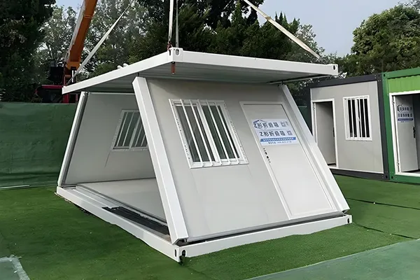
KUBO’s published system pages illustrate why system-specific limits matter. Its flat pack and detachable container categories currently publish “Up to 3 Storeys*” as planning references for selected configurations, subject to project engineering; the detachable page states that selected stacked arrangements require structural, stair, egress and foundation review. Its folding container category describes single-storey use as typical and states that stacking requires a dedicated system and engineering confirmation. These are planning boundaries, not a universal rule for modular buildings.
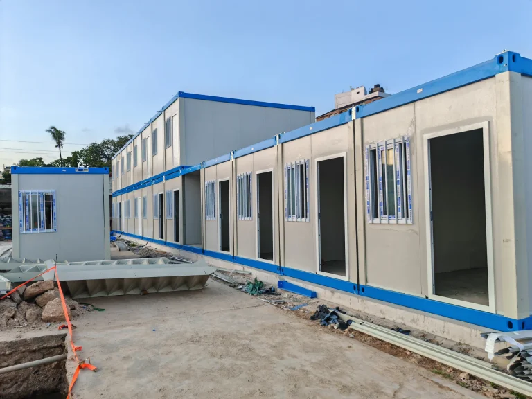
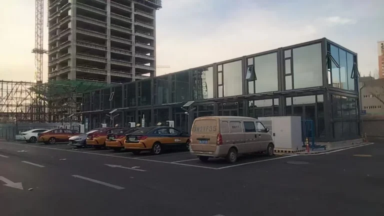
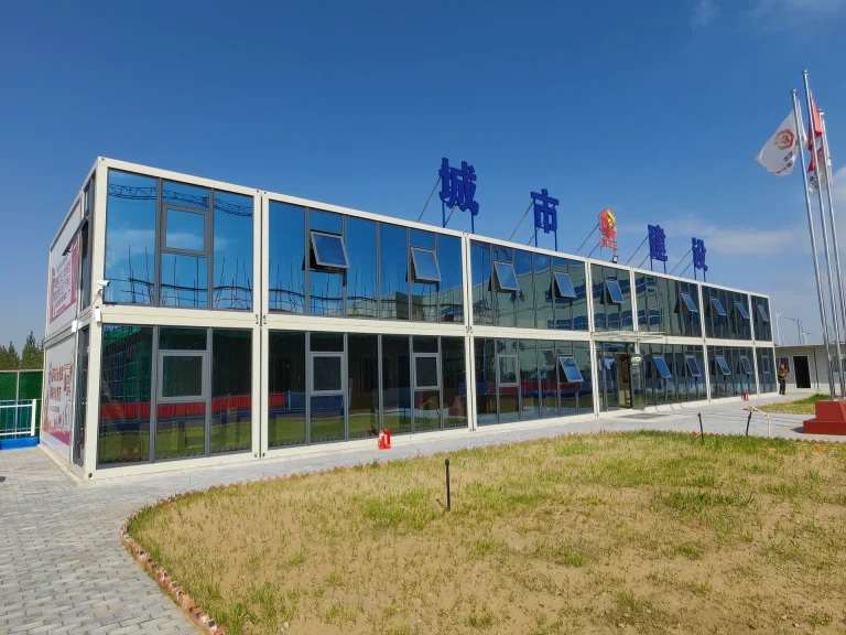
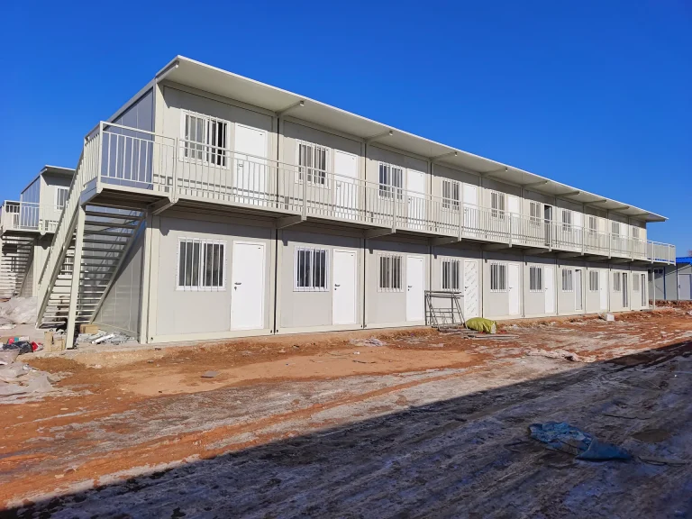
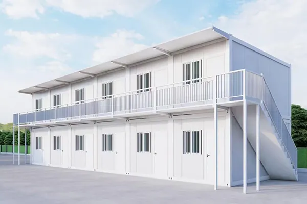
KUBO also has project photographs showing two-storey dormitory arrangements, external stairs and elevated access galleries, an internal stair configuration and stacked modules. Those images are useful evidence of relevant configuration experience, but they do not establish the permissible load, connection capacity, fire resistance, escape compliance, accessibility or authority approval of a future project.
Multi-Storey Decision Matrix: Land Efficiency Versus Added Interface Risk
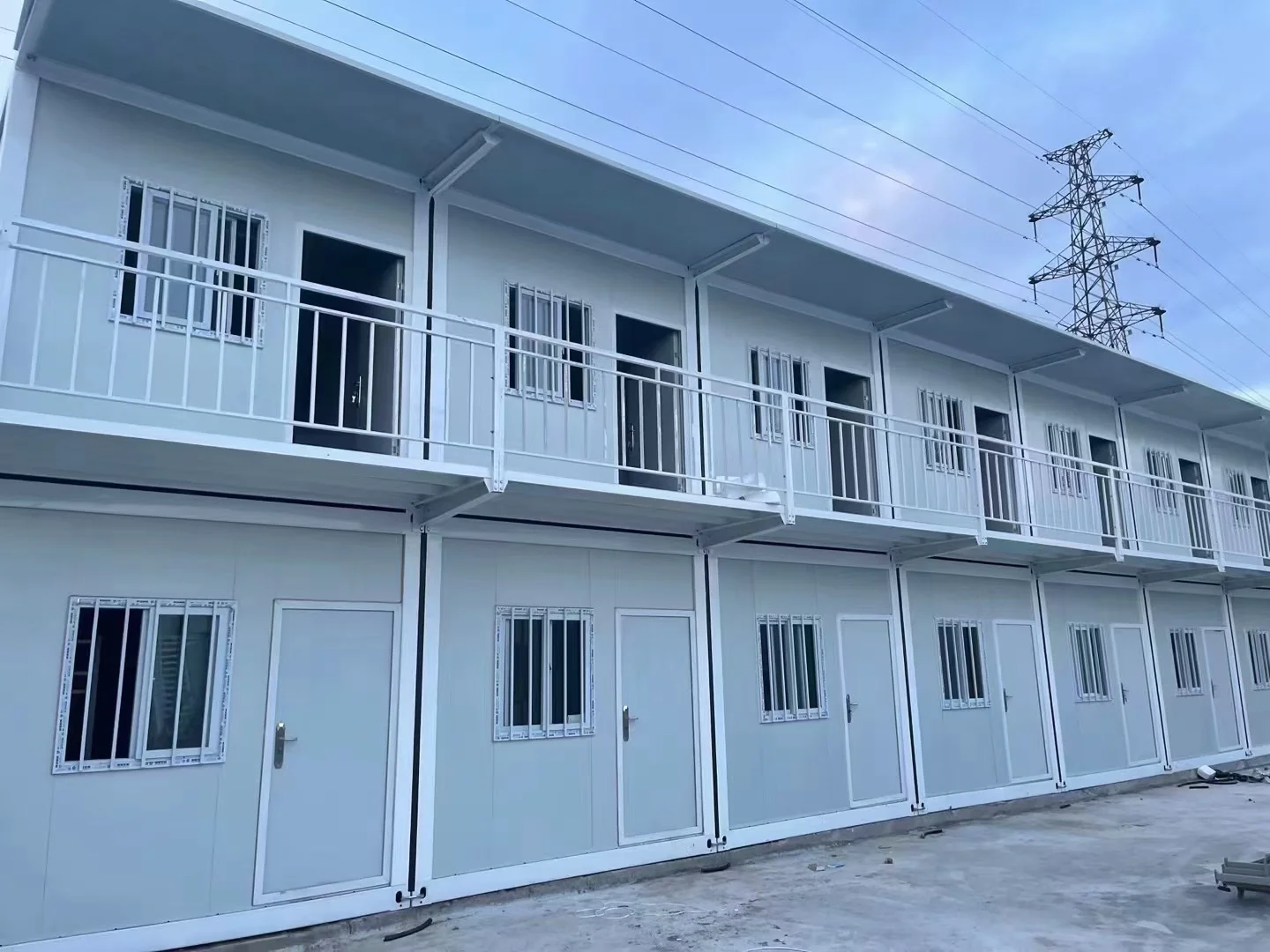
The matrix below is intended for concept-stage comparison. It does not prescribe a storey limit. “Higher stacked configuration” means a project-specific arrangement that the selected product system and engineering review actually support.
| Decision factor | Predominantly single-storey accommodation | Two-storey modular accommodation | Higher stacked configuration, where specifically engineered | Why it matters to the buyer/EPC |
| Land use | Largest footprint for the same room count | Can materially reduce building footprint | Can reduce footprint further | Valuable on constrained compounds, but land savings must be compared with access, fire, lifting and service needs |
| Structural coordination | Loads and lateral system usually have fewer vertical interfaces | Requires defined stacking, connection, bracing and foundation load paths | Vertical accumulation and stability coordination become more demanding | Late structural changes can affect modules, anchors, foundations and erection method |
| Stairs and landings | Limited or no inter-storey circulation | Stair position, landing geometry, guarding and door interfaces become core layout inputs | More occupants depend on vertical circulation and escape strategy | Circulation cannot be added as an accessory after room modules are frozen |
| Egress and fire strategy | Routes may be simpler, subject to local rules | Escape from upper level must be integrated with layout and fire strategy | Approval complexity may increase with height, size, use and construction method | Authority engagement and design evidence may need to begin earlier |
| Accessibility | Mostly horizontal route planning | Vertical access strategy must be defined for the applicable building use and jurisdiction | May require more extensive accessible-route coordination | Accessibility can change stairs, ramps, lifts, room allocation and site grading depending on local requirements |
| Vertical MEP | Services can often remain local or run horizontally outside rows | Risers, floor penetrations, drainage falls, isolation and access points must be coordinated | More stacked connections and cumulative service loads/interfaces | MEP changes can conflict with structure, fire stopping and weather sealing |
| Weather exposure | Roof and ground interfaces dominate | Galleries, stair towers, joints, canopies and level-to-level drainage add exposure | More façade and access interfaces need durable detailing | Water at circulation interfaces can affect safety, envelope durability and maintenance |
| Installation | Repetitive placement with fewer elevated interfaces | Requires lifting, alignment, connection, temporary access and sequencing between levels | More dependence on erection engineering and controlled hold points | Site capability and crane/logistics planning become part of system selection |
| Approval risk | Project-specific but often fewer vertical-system questions | More disciplines must converge before approval | Greater possibility of project-specific evidence requirements | Unresolved approval inputs can delay drawing freeze or trigger redesign |
| Relocation/reuse | Often simplest to dismantle or move by zone | Stairs, galleries and vertical services must be included in dismantling plan | Reconfiguration can become increasingly project-specific | “Relocatable” should be tested against actual dismantling and recommissioning scope |
| Overall interface risk | Low to moderate depending on project | Moderate to high if interfaces are not frozen together | Potentially high unless system and project are designed for it | The commercial comparison should include engineering, site works and approvals, not only module price |
A project should choose multi-storey accommodation because its full building configuration creates value, not because stacking appears to increase density at negligible cost. The savings in land can be offset by stairs, steelwork, foundations, cranage, protective roofs or canopies, additional service coordination, more detailed installation controls and a longer approval path. No universal cost or schedule penalty can be stated responsibly because those effects depend on project geometry, jurisdiction, labor, logistics and the selected modular system.
Structural Coordination: Follow the Load Path Beyond the Module Frame
Vertical load path and module-to-module connections
The structural question begins with the complete load path. The upper module does not “sit on” the lower one in an informal sense; the design must establish where vertical actions enter the upper module, how they transfer through columns or other primary elements, how module-to-module interfaces behave, and how the forces continue through lower levels into the foundations.
This makes connection definition a production issue as well as a calculation issue. Connection plates, bolts, welds, locking devices, bearing interfaces, tolerances and erection access—whatever the approved system uses—must correspond to controlled drawings and an installation method that can be executed on site. A connection that is structurally adequate on paper can still become an installation risk if crews cannot access it, if module alignment is poor, or if the inspection point is concealed before verification.
For procurement, request the project-specific design basis, general arrangement, stacking/connection details and the defined inspection or hold points. Do not treat a catalogue statement such as “stackable” as a substitute for this package.
Lateral stability, bracing and building-level behavior
Wind and seismic actions, where applicable, must be resolved at the building level. The relevant issue is not only whether an individual module has a frame, but how the complete stacked block resists lateral actions and transfers them to the ground. The design may rely on module frames, bracing, diaphragms, connection behavior, supplemental structural elements or a combination; the correct solution is system- and project-specific.
Open corridors, stair towers, large door or window openings, joined modules and irregular block shapes can all influence the lateral system. A procurement team should therefore avoid freezing architectural layouts independently of structural review. If a late corridor opening removes a bracing location, the consequence may not be a simple drafting change—it can propagate into steelwork, connection details, foundations, fabrication and erection.
KUBO’s flat pack page states that high-wind and seismic inputs should be provided before bracing, anchorage, stacking and connections are adjusted through engineering review. It also makes local approval and project-specific calculations part of the engineering boundary.
Foundations: more than “the same pads with more weight”
Multi-storey buildings can change reactions at foundations, but it is unsafe to assume a simple multiplier. Foundation design depends on the structural scheme, module spacing, load combinations, site wind/seismic criteria, soil conditions, settlement behavior, drainage, frost or other local effects, and the way anchors or base connections transfer actions.
The manufacturer can provide building reactions or interface information within the agreed engineering scope. The buyer/EPC and locally authorized engineer normally need site survey, geotechnical information and local foundation design. KUBO’s workforce accommodation page similarly separates factory supply from local survey, geotechnical work, foundations, external utilities and permitting, while identifying module-to-foundation interfaces as jointly coordinated items.
This is a common commercial gap: one quotation includes only the modular superstructure, while another includes additional foundation information, local engineering support or installation supervision. Those offers are not directly comparable until the scope boundary is normalized.
Stairs, Landings, Corridors and Egress Must Be Designed as One Circulation System
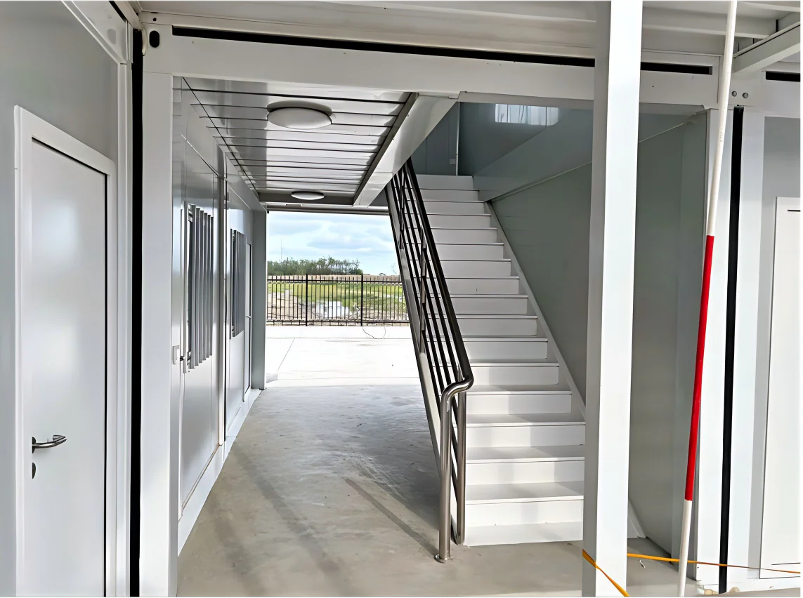
In multi storey modular accommodation, stairs are not simply purchased as an external accessory. They interact with door positions, landing levels, corridor widths, guardrails, weather exposure, lighting, drainage, structural attachment, escape strategy and daily occupant movement.
The circulation concept should answer practical questions before detailed module production begins. Where do residents leave each room? Do they enter an internal corridor or an external gallery? How many routes from the upper level are required by the applicable code and fire strategy? Where do stair flights discharge? Do doors open onto landings? Can occupants move safely during rain, dust, snow, darkness or maintenance? Does the route conflict with vehicle movement, drainage channels, utility equipment or future camp expansion?
England’s Approved Document K is a jurisdiction-specific example of why stair design cannot be reduced to one dimension: the guidance covers staircases, ladders, ramps, guarding and protection from falling/collision in and around buildings. Approved Document M separately provides an accessibility baseline for access to and use of buildings in England. These documents should not be exported as universal design rules, but they illustrate the disciplines that need to be resolved under the actual destination’s regulations.
U.S. OSHA construction rules offer another limited but useful example for the erection stage. OSHA 29 CFR 1926.1052 addresses construction stairways, including uniform treads/risers, platforms where doors open directly onto stairways, temporary treads/landings and rails/handrails. Those provisions apply in their U.S. construction context; they are not a substitute for the building’s permanent egress design or another jurisdiction’s code.
External galleries and weather protection
External stairs and access galleries are common ways to serve stacked accommodation because they can preserve internal room area and simplify some circulation layouts. They also create an exposed interface that needs deliberate weather and maintenance planning.
Rainwater should not be allowed to collect at landings, thresholds or gallery joints. Drainage paths should be coordinated with columns, foundations, walkways and site drainage. In cold or dusty environments, the project may need to consider slip risk, snow/ice, contamination or cleaning access under local requirements and operating procedures. Roofs, canopies or screens may improve usability but can add wind area, structural attachment points and drainage interfaces.
The right solution depends on climate, occupancy pattern and local code. What matters for procurement is that weather protection is shown on the coordinated building drawings rather than left as an undefined site addition.
Accessibility is a project input, not a late compliance overlay
A multi-level dormitory may require an accessibility strategy that affects room allocation, routes and vertical movement. The exact obligation depends on jurisdiction, building classification, project use and authority interpretation. Project teams should establish those requirements before deciding that all accommodation can be placed on upper levels or that stairs alone are sufficient.
For England, Approved Document M provides guidance on access to and use of buildings and distinguishes between dwellings and buildings other than dwellings. That illustrates why the building’s regulatory classification matters; the destination’s own rules and appointed professionals must determine the actual design.
Fire Strategy: Modular Construction Does Not Remove Building-Level Responsibilities
Fire strategy becomes especially important when sleeping accommodation is stacked because occupants on upper levels depend on defined escape routes and because services, joints and penetrations may cross compartments or protected construction. The correct fire strategy can influence module layout, panel/lining selection, corridor arrangement, stair position, doors, penetrations, cavity or void treatment, alarms and other systems required by the applicable jurisdiction.
The GOV.UK Approved Document B FAQ is useful as an England-only example because it specifically discusses unusual structural approaches such as volumetric modular construction. It advises designers to agree design intent and necessary evidence with the building control body before work starts, and it notes that height, size, use, unusual internal fire-spread routes and alternative structural failure mechanisms can require additional consideration. That is not a statement that modular construction is inherently unsafe; it is a reminder that an unfamiliar structural or fire behavior should be justified for the specific design rather than assumed equivalent.
For an EPC or owner, this has a direct schedule implication. If the fire strategy is unresolved when the manufacturer freezes openings, wall build-ups, service routes and stair geometry, later authority comments can require changes to several factory-controlled packages at once. The safer sequence is to establish the regulatory basis, design intent and evidence responsibilities before production release.
Vertical MEP Coordination: Services Become a Stack of Interfaces
A modular dormitory multi storey layout often concentrates wet services and utility connections vertically, which can be efficient when planned deliberately. The same arrangement can become difficult to install and maintain if risers, offsets and penetrations are discovered after the structural grid and room modules are fixed.
Define risers and connection zones early
The project should map water supply, sanitary drainage, venting, electrical distribution, communications, HVAC connections and any other required services through the building. The scope must distinguish what is factory-installed within modules, what terminates at module interfaces, what runs in site-installed risers or corridors, and what connects to the external camp utility network.
For stacked wet areas, vertical alignment can reduce unnecessary offsets, but only if the architectural room schedule supports it. If bathrooms shift position between floors, drainage and vent routes may need offsets that consume ceiling or service space and create additional penetrations. Similarly, electrical risers need access, segregation and coordination with fire and structural requirements.
Control penetrations as multidisciplinary changes
A hole through a floor, wall, roof or structural member is not merely an MEP detail. It can affect structural capacity, fire stopping, air/water sealing, acoustic separation and factory production. Penetrations should therefore be revision-controlled against coordinated drawings. Site teams should not create unapproved openings to “make the pipe fit” unless the responsible designers have reviewed the change.
This is one of the strongest arguments for model or drawing coordination before production. The objective is not necessarily to use sophisticated software; it is to make each penetration, sleeve, access panel and connection point traceable to an approved interface.
Commission by system and by level
Commissioning should prove more than whether an individual room has power and water. The team needs a plan for pressure testing or other applicable service checks, drainage function, electrical testing, HVAC operation, controls, alarms and any required life-safety systems across the connected building. The exact tests depend on scope and jurisdiction.
For multi-level plumbing, hidden connections and vertical joints should be inspected before they are enclosed or become inaccessible. For electrical systems, factory and site portions need a clear responsibility split so there is no gap between the module distribution and the site’s permanent or temporary utility system.
Vertical Interface Map: What Must Be Coordinated Across Levels
This interface map can be used during design reviews and supplier clarification meetings.
| Vertical interface | What must be defined | Key coordination question | Typical consequence if unresolved |
| Load path | Primary members, bearing points, vertical reactions | Where does each upper-level action transfer to the foundation? | Local overstress, redesign, connection/foundation changes |
| Module-to-module connection | Connection type, access, tolerances, inspection | Can the connection be installed and verified in the approved erection sequence? | Misalignment, inaccessible fasteners, delayed stacking |
| Lateral stability | Bracing/frames/diaphragm assumptions and anchors | Does the final architectural layout preserve the intended lateral system? | Structural redesign or added bracing |
| Foundations | Reactions, anchors, levels, tolerances, geotechnical basis | Are site foundations designed for the actual stacked configuration? | Differential levels, anchor mismatch, delayed erection |
| Stairs and landings | Geometry, support, door interfaces, guarding | Is circulation integrated with architecture and egress rather than added later? | Rework, blocked doors, unsafe transitions |
| Egress | Occupant route, discharge, fire strategy, local requirements | Can occupants leave upper levels under the approved strategy? | Authority rejection or major layout revision |
| Accessibility | Applicable route and accommodation requirements | Which levels and facilities must be accessible under local rules? | Late addition of ramps/lifts or room reallocations |
| Vertical MEP | Risers, penetrations, isolation, access, testing | Which services are factory-installed and which are site-connected? | Clashes, site cutting, incomplete commissioning |
| Weather protection | Galleries, canopies, thresholds, drainage | Where does rainwater/snowmelt go at elevated circulation areas? | Slip risk, leakage, corrosion or maintenance burden |
| Fire stopping | Penetrations, joints and interfaces within fire strategy | Who supplies and verifies the required treatment at factory/site interfaces? | Unverified compartmentation or delayed handover |
| Installation access | Crane reach, lifting sequence, temporary access | Can upper modules, stairs and galleries be safely installed in sequence? | Site congestion, resequencing, extra lifts |
| Commissioning | Hold points, inspections, service tests, records | What must be witnessed before areas are enclosed or occupied? | Hidden defects or incomplete handover evidence |
The value of this map is not that every project will use the same technical solution. It forces the team to identify who owns each interface and when it must be resolved.
Responsibility Matrix: Keep Factory Scope and Local Statutory Scope Visible
Multi-storey procurement often fails at boundaries rather than inside a single discipline. The following matrix is a practical starting point; the contract and local law must define the actual obligations.
| Workstream | Buyer / EPC | Modular manufacturer | Site contractor | Local engineer / designer | Authority / building control |
| Project design basis, use and occupancy | Leads and approves requirements | Uses approved inputs for product engineering | Provides constructability/site input | Interprets local technical requirements | Confirms regulatory/approval expectations as applicable |
| Site survey and geotechnical data | Procures/provides | Uses interface data when required | Supports field information | Reviews/designs site works | Reviews within local process where applicable |
| Module structural design | Defines required criteria and deliverables | Designs/manufactures within contracted system scope | Installs to approved method | Reviews/adapts/coordinates as locally required | Accepts through applicable approval route |
| Foundations and anchors | Defines scope and appoints responsible party | Provides reactions/interface details by agreed scope | Constructs and records as-built condition | Designs/verifies to site and local code | Reviews/inspects as required |
| Stairs, galleries and guarding | Defines functional/occupancy requirements | Supplies agreed components and drawings | Installs, aligns and completes site interfaces | Confirms local compliance and integration | Reviews where required |
| Fire and egress strategy | Appoints responsible design team; sets use | Coordinates module materials/openings/interfaces to approved strategy | Executes site fire stopping and interfaces within scope | Leads or validates local fire/egress design as applicable | Reviews/approves under local process |
| Accessibility | Defines user/project requirements | Incorporates approved module-side provisions | Builds external route/site works | Confirms local accessibility solution | Reviews under local process |
| MEP module services | Defines utilities and performance basis | Provides factory-installed scope and interface points | Connects site-side systems and performs field work | Coordinates local design, sizing and compliance | Inspects/approves as required |
| Erection method and temporary works | Coordinates site program and resources | Provides system installation information; support as contracted | Leads site execution and temporary conditions unless otherwise contracted | Reviews temporary/permanent design where required | Enforces local construction requirements |
| Commissioning and occupancy | Accepts handover and appoints operators | Supplies agreed factory records | Performs site testing/rectification within scope | Verifies design compliance where required | Grants occupancy/approval where applicable |
KUBO’s workforce accommodation page uses a similar scope principle: factory supply covers modular system configuration, drawings, production, inspection, export packing and agreed support, while local project scope typically includes survey, geotechnical work, permits, foundations, external utilities, cranage, installation labor and commissioning. Joint interfaces include design criteria, module-to-foundation connections, utilities and acceptance responsibilities.
Release-Gate Table: Do Not Let Procurement Outrun Engineering Maturity
A multi-storey block should move through explicit release gates. The exact documents vary, but the logic prevents factory work from freezing around assumptions that the local project team has not yet approved.
| Release gate | Minimum issues to resolve before release | Evidence to retain | What should stop the release |
| Gate 1: Concept / system selection | Site footprint, resident capacity, preliminary storey strategy, system category, regulatory basis, preliminary stairs/egress concept, utilities and site logistics | Approved design brief, concept layout, responsibility split, open-issue register | Unknown project use, no local code path, untested site constraints, no agreement on who designs foundations/fire/egress |
| Gate 2: Production design freeze | Module schedule, structural basis, stacking and connection details, openings, stairs/landings, service routes, penetrations, materials, critical fire/accessibility interfaces | Revision-controlled drawings, calculations/deliverables by agreed scope, BOM/material schedule, interface schedule | Unapproved structural or fire assumptions, moving stair positions, unresolved risers, missing foundation reactions, uncontrolled penetrations |
| Gate 3: Shipment release | Factory inspections complete, module/part coding confirmed, protection/packing sequence aligned with erection plan, required documents issued | Inspection records, packing list, loading sequence, release record, installation information | Nonconformities affecting erection, missing critical parts, unapproved revisions, packing sequence incompatible with site installation |
| Gate 4: Stacking / upper-level erection | Foundations accepted, lower modules aligned, required connections/anchors inspected, crane/access plan active, temporary stability and safe access established | Foundation/as-built checks, connection inspections, lift/installation records, hold-point sign-off | Out-of-tolerance foundations, incomplete lower-level connections, unsafe temporary access, missing components, unresolved field changes |
| Gate 5: Occupancy / handover | Stairs/guarding complete, egress routes clear, MEP commissioned, fire/accessibility requirements addressed, weather interfaces closed, authority and client acceptance completed as applicable | Commissioning records, inspection/approval documents, as-built drawings, O&M/maintenance information | Incomplete life-safety work, untested services, open structural issues, missing statutory acceptance, unsafe access or unresolved water ingress |
This release logic is particularly valuable when production is geographically separated from the project site. It creates a shared language for the manufacturer, EPC, site team and local professionals: “ready to fabricate” and “ready to occupy” are different states, with different evidence.
Compare the Full Project Path, Not Only the Number of Modules per Hectare
Multi-storey and single-storey concepts should be compared across the project lifecycle. The importance of each factor changes by site, so the table uses qualitative directions rather than invented cost or schedule numbers.
| Evaluation dimension | Single-storey bias | Multi-storey bias | Decision test |
| Lifecycle | Simpler access and fewer vertical components can favor temporary or easily reconfigured camps | Can favor long-duration constrained sites if vertical infrastructure is justified | How long will the block operate, and will stairs/services be reused? |
| Scalability | Expansion usually consumes more land but can be straightforward by adding rows | Vertical expansion may not be available after initial design; horizontal/vertical future states must be pre-engineered | Is future growth reserved in the original structural and utility plan? |
| Schedule certainty | Fewer stacked interfaces can reduce erection dependencies | Can remain predictable if drawings, foundations and erection sequence are mature; late changes have larger propagation effects | Are the key interfaces frozen before production? |
| Local-labor dependency | More repetitive ground-level work | Requires competent elevated installation, alignment, connection and stair/gallery work | Does the local crew have the method, supervision and equipment required? |
| Logistics | More spread-out foundations and site distribution | Additional stairs, galleries and structural/access components may complicate sequencing | Can packing and unloading follow the erection order? |
| Site readiness | Larger prepared footprint | Smaller footprint but higher sensitivity to foundation level/anchor coordination and crane access | Which site constraint is actually dominant: land, groundworks, access or lifting? |
| Utilities | Horizontal distribution may be longer | Vertical risers can consolidate services but increase penetrations and stacked interfaces | Is the MEP scheme intentionally vertical, or being adapted late? |
| Approval | Potentially simpler geometry, still jurisdiction-specific | May attract additional review depending on height, use, fire strategy and construction system | Has the authority/design team accepted the intended approach early? |
| Maintenance | Ground-level access can be easier | Stairs, galleries, elevated seals and risers add inspection points | Can maintenance staff safely access critical components? |
| Relocation | Blocks can often be removed independently if utilities allow | Dismantling must include elevated circulation and vertical services | Is relocation a real lifecycle requirement or only a marketing assumption? |
| Interface risk | More interfaces spread across site, fewer stacked dependencies | Higher concentration of structural, egress, service and erection interfaces | Which configuration has the lower total project risk after site works are included? |
This comparison is particularly important for remote camps. A compact stacked block may solve a land problem but create a crane or approval problem. A single-storey layout may appear less efficient but be easier to phase, relocate or maintain. The correct decision depends on the project’s dominant constraint.
A Practical Evaluation Workflow for a Two Storey Worker Camp or Stacked Dormitory
1. Stabilize the accommodation brief before choosing the vertical form
Define resident groups, peak and phased headcount, room occupancy, bathroom strategy, shared facilities, operating duration, shift patterns and expansion plan. KUBO’s workforce accommodation planning page emphasizes this sequence: establish people, rooms, shared facilities, climate, utilities and phases before selecting the building system.
A multi-storey layout should respond to that brief. It should not be the starting assumption simply because a supplier has stackable modules.
2. Fix the regulatory and engineering basis early
Identify the destination jurisdiction, building use, local design actions, fire/egress requirements, accessibility requirements, approval route, geotechnical basis and responsible design professionals. If inputs are not yet available, keep the scheme explicitly preliminary rather than allowing temporary assumptions to become production information.
3. Coordinate the vertical interface map before detailed production drawings
Run a focused review across structure, stairs, egress, accessibility, MEP, weather protection, foundations and installation. Each interface should have an owner, an input, an output and a required date. This is more useful than a generic “coordination complete” status because it exposes unresolved handoffs.
4. Freeze repeatable modules, but do not hide special modules
Standardization is valuable in worker camps because repeated room modules reduce unique production and site tasks. Multi-storey blocks still contain special conditions: stair-adjacent modules, corridor ends, riser modules, service rooms, corner/braced bays or other system-specific variants. These should be identified in the module schedule rather than forced into a false “all units are identical” assumption.
5. Align packing and erection with the building sequence
If a lower-level component is packed behind upper-level modules or if stair parts arrive after the site needs safe access, logistics can disrupt installation. The packing list, module codes and loading sequence should therefore reflect the intended erection plan. KUBO’s flat pack page describes controlled packing, visible unit numbering and alignment of packing with site installation as part of project execution.
6. Use hold points before interfaces become inaccessible
Foundations, anchors, module-to-module connections, concealed MEP joints, fire stopping and other critical interfaces should be inspected at the stage defined by the project quality plan. The principle is simple: do not cover or stack over an interface that still needs verification.
What Buyers Should Request from a Modular Manufacturer
A MOFU comparison should test document maturity and interface control, not only product appearance. For multi storey modular accommodation, ask shortlisted manufacturers to return the same project brief and identify assumptions, exclusions and deviations.
The evidence package may include, according to contracted scope:
- project-specific general arrangement and module schedule;
- design basis and structural deliverables appropriate to the supplier’s responsibility;
- stacking, connection, bracing and anchorage interface details;
- stair, landing, gallery and guarding drawings where supplied;
- module-to-foundation reactions or connection data needed by the local engineer;
- material/component schedule and controlled opening schedule;
- MEP interface drawings showing factory and site scope;
- penetration and riser coordination information;
- installation sequence and lifting/interface requirements;
- inspection and release plan with defined hold points;
- packing list, module/part coding and loading sequence;
- commissioning/handover documentation within the agreed scope.
Do not ask a manufacturer to “guarantee local compliance” without defining who is responsible for local design, submission and statutory approval. Equally, the manufacturer should not hide behind a generic statement that “local work is by others” when its module geometry, connections, materials or service interfaces are inputs to the local design. A usable scope matrix makes those dependencies visible.
Review a Multi-Storey Configuration Before Freezing the Module Order
If your project is considering a two-storey worker camp, modular dormitory multi storey block or another stacked prefab accommodation layout, prepare the destination country, project stage, required resident capacity, room/bathroom mix, site plan, preliminary building footprint, proposed number of levels, climate/design inputs available, utility concept, fire/egress/accessibility requirements known to date, foundation/geotechnical status, erection resources and target project sequence.
KUBO can use that information to review the modular configuration and clarify which assumptions need project-specific engineering before quotation or design freeze. Start with the Flat Pack Container House system reference if you are comparing stackable camp systems, or review the workforce accommodation planning framework if the room and facility brief is still being developed. When the project inputs are ready, use the project enquiry page to review a multi-storey configuration.
Frequently Asked Questions
1. What makes multi storey modular accommodation different from single-storey modular housing?
The difference is not simply adding another row of modules above the first. A multi-storey building creates vertical structural load paths, stacking connections, upper-level circulation, egress dependencies, vertical service routes and more demanding installation interfaces. The design also has to coordinate foundations, weather protection, fire strategy, accessibility and commissioning as a building-level system. Whether that added complexity is justified depends on site constraints and project requirements.
2. Is a two storey worker camp always more land-efficient?
It can reduce the building footprint needed for a given room count, but the total site benefit depends on stairs, access galleries, fire separation, roads, utilities, drainage, crane access and required open space. A smaller building footprint does not automatically mean a smaller or cheaper camp. Compare the complete compound layout and site works, not only the accommodation module footprint.
3. How many storeys can modular accommodation be stacked?
There is no responsible universal answer. Storey limits depend on the specific modular system, approved configuration, structural design, site actions, connections, foundations, fire/egress strategy and local approval. KUBO currently publishes “Up to 3 Storeys*” as a reference planning value for selected flat pack configurations, with the final limit subject to the approved model, options, site method and engineering review; other KUBO systems use different planning boundaries.
4. Can project photos prove that a supplier’s modules are suitable for my multi-storey building?
No. Photos can demonstrate that the supplier has produced or delivered a visible type of stacked arrangement, stair or gallery configuration. They do not prove the structural capacity, connection performance, fire resistance, egress compliance, accessibility or authority approval required for a new site. Use photos as experience evidence, then request project-specific drawings, calculations or other agreed engineering evidence.
5. Should stairs be supplied by the modular manufacturer or a local contractor?
Either arrangement can work if the interface is clearly defined. The critical points are who designs the stair to the applicable requirements, who provides structural supports and connections, who coordinates landing levels and door swings, who installs guarding and weather protection, and who verifies the final assembly. A split package without an interface drawing is higher risk than either a fully coordinated factory package or a clearly engineered local package.
6. Why do vertical MEP services create more coordination risk in stacked prefab accommodation?
Services cross module and floor boundaries. Drainage, vents, water, electrical feeders, HVAC and communications may require risers, penetrations, offsets, isolation points and access panels that interact with structure, fire stopping, waterproofing and maintenance. If these routes are not coordinated before production, the site team may face clashes or be tempted to create unapproved penetrations.
7. Do stacked modules require different foundations?
They may require different reactions, anchorage or foundation arrangements, but the result cannot be determined from storey count alone. The foundation solution depends on the actual structural scheme, site actions, soil/geotechnical conditions, settlement criteria, drainage and local design requirements. The modular supplier and local foundation engineer should exchange defined reactions and interface information rather than rely on a generic pad detail.
8. How should fire and egress be handled for a modular dormitory multi storey project?
Begin with the destination jurisdiction, building classification, occupant use and approval route. The fire/egress strategy should then inform stairs, corridors, doors, materials, penetrations, alarm or other required systems, and the evidence package. England’s Approved Document B FAQ is one example showing that unusual structural approaches such as volumetric modular construction may require early agreement of design intent and evidence; other jurisdictions will have their own requirements.
9. Are external access galleries a good choice for multi-storey accommodation?
They can be effective because they keep circulation outside the room modules and can simplify repeated dormitory layouts. Their suitability depends on weather, structural attachment, guarding, drainage, lighting, slip resistance, maintenance and the local fire/egress strategy. Exposed circulation should be designed as part of the building, not added after the module layout is complete.
10. What should be frozen before manufacturing a multi-storey modular block?
At minimum, the project should have controlled versions of the module schedule, building arrangement, design basis, stacking/connection strategy, critical structural interfaces, stairs/landings, openings, MEP interface points, risers/penetrations, relevant fire/accessibility inputs, materials and inspection requirements. Foundation interface data and responsibility boundaries should also be defined. If any of these remain open, the production release should state the assumption explicitly and assess the redesign risk.
Sources and References
- KUBO Flat Pack Container House — published system planning values, multi-storey engineering boundary, scope and release information
- GOV.UK Approved Document K — protection from falling, collision and impact in England
- GOV.UK Approved Document M — access to and use of buildings in England
- GOV.UK Approved Document B fire-safety FAQ — England guidance including volumetric modular construction considerations
- U.S. OSHA 29 CFR 1926.1052 — construction-stage stairway requirements