


Summary
Flat pack container house components form a coordinated building assembly, not a collection of interchangeable beams, panels and finishes. The floor frame transfers loads and supports the floor build-up; columns and roof members establish the structural enclosure; panels, insulation, roof sheets, trims and seals manage weather and indoor conditions; openings and service interfaces connect the module to its intended use.
For procurement teams, the critical question is not merely whether each visible component is included. It is whether the approved configuration defines the component variant, its function, its factory preparation, its package identity, its site interface and the party responsible for completing and verifying that interface.
This article examines KUBO’s flat pack module anatomy using manufacturer catalogue evidence, factory reference views and established building-science principles. Catalogue dimensions and material descriptions are treated as reference examples—not universal specifications, structural guarantees or substitutes for project drawings.
A Module Is More Than Its Visible Parts
A flat pack module can look straightforward in an exploded illustration: a lower frame, floor layers, four corner columns, walls, windows, a roof assembly and several trim pieces. That visual simplicity is useful for explaining the system, but it can hide three important distinctions.
The first is the difference between primary or secondary structure and finishes. Perimeter beams, columns, corner regions, tie members and secondary C-section members participate in supporting or distributing loads. Cement-fiber board and PVC floor finish occupy the same lower assembly, but they perform different roles. A wearing surface is not a structural deck, while board thickness by itself does not establish the allowable floor load.
The second distinction is between individual materials and whole-assembly performance. A wall panel core may contribute thermal or fire-related characteristics, but it does not, by itself, define the complete wall’s thermal transmittance, air leakage, fire resistance, acoustic performance or behavior around openings. Steel framing, joints, fasteners, panel edges, seals and service penetrations all affect the result.
The third is the boundary between factory preparation and site completion. A manufacturer may fabricate frame assemblies, prepare openings, provide panels, pack trims and provision service interfaces. The final building can still depend on site foundations, anchorage, structural joining, joint sealing, drainage continuity, utility connections, testing and local approval.
This is why an apparently complete package can still carry an incomplete scope. “Floor included,” “electrical included” or “roof supplied” may describe physical content without defining the approved variant, installed condition, interfaces, testing boundary or responsible party.
The KUBO flat pack system overview provides the broader system-selection context. The anatomy below deals with the narrower question of what sits inside the system and what each part means for project release and site completion.
Reading the KUBO Component Illustration
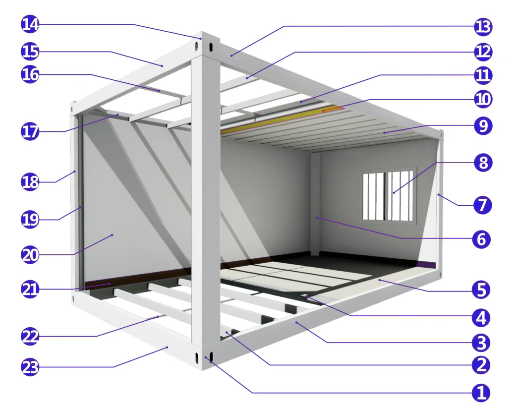
KUBO’s numbered cutaway illustration shows a reference flat pack module separated into functional layers. It is a component illustration rather than a fabrication drawing, approved bill of materials or photograph of one completed project module. The numbers help viewers locate parts, but ambiguous translated labels should not be converted into invented fabrication terminology.
A more reliable reading method is to group the visible components by function:
-
The lower structural group includes corner fittings, long and short perimeter members, ties and secondary C-section members.
-
The floor group includes a 19 mm cement-fiber board reference and a 2 mm PVC floor finish reference.
-
The vertical and upper structural group includes columns, roof perimeter members, secondary roof members and associated connection regions.
-
The roof and drainage group includes insulation, a profiled ceiling sheet, an outer roof sheet and a drain pipe.
-
The enclosure group includes wall panels, windows and the interfaces formed around openings.
-
The completion group includes trims, skirting, seals, fasteners and service-interface details that may be easy to overlook in an exploded view.
The following matrix distinguishes what the manufacturer reference actually shows from what a buyer still needs to confirm.
| Functional group | Physical evidence in the KUBO reference | What the buyer should confirm | Why an undefined item matters |
|---|---|---|---|
| Floor frame and connections | Bottom corner fittings, perimeter members, tie members and secondary C-section members are depicted. | Member schedule, section geometry, steel grade and thickness by member, connection type, support points, load basis, anchorage interface and released structural drawings. | A general frame description does not establish how each member carries load or connects to foundations, adjacent modules and upper levels. |
| Floor board and wearing surface | A 19 mm cement-fiber board and 2 mm PVC finish are identified in the reference configuration. | Approved board type, support spacing, edge treatment, joint arrangement, moisture exposure, finish specification, adhesives or fixing method, room use and project floor-load criteria. | Board thickness alone does not prove floor capacity. A wearing surface may resist ordinary traffic yet require different detailing in wet, sanitary or heavy-equipment areas. |
| Columns and roof frame | Vertical columns, trims and upper perimeter or secondary members appear in the illustration. | Column and roof-member geometry, connection plates or fasteners, bracing, stacking conditions, lifting restrictions, design actions and project-specific structural calculations. | Large openings, stacking, high wind, snow or seismic requirements can change forces and detailing even when the external module shape looks similar. |
| Roof layers and drain path | A profiled ceiling sheet, fibrous insulation, 0.45 mm outer roof sheet reference and drain pipe are shown. | Approved roof build-up, slopes, laps, flashings, drainage outlets, condensate strategy, penetrations, sealants, overflow approach, maintenance access and site joint completion. | A roof sheet is only one part of the water-management path. Discontinuity at module joints, penetrations or outlets can undermine the assembly. |
| Walls, doors and windows | Wall panels and windows are visible; catalogue views depict reference wall-panel options. | Panel thickness and core, facing material, coating, opening schedule, frame interfaces, sill and head details, hardware, glazing, security, local performance criteria and replacement access. | A changed opening can affect structure, water control, air control, heat flow and interior layout simultaneously. |
| Seals, trims and skirting | Columns or trims and skirting are depicted, although every seal and fixing is not separately legible. | Joint map, trim profiles, seal types, compatible substrates, factory-applied versus field-applied scope, color, spare quantity and inspection method. | Small completion parts often close the visible and environmental interfaces between larger components. Missing or mismatched pieces can delay enclosure completion. |
| Service interfaces | Service routes are not fully defined by the cutaway illustration. | Electrical voltage and frequency, distribution boundary, outlet and lighting schedules, plumbing points, sanitary connections, HVAC openings, earthing, external utility entry and testing responsibility. | “MEP provision” may mean a prepared opening, internal rough-in, installed fixture or tested system. Those are materially different scopes. |
The matrix is not a substitute bill of materials. It is a way to turn a component illustration into project questions without assigning unsupported properties to the image.
How the Structural Parts Work Together
Floor perimeter frame, secondary members and corner regions
The lower steel assembly provides the base from which the module is supported, joined and enclosed. Perimeter members define the frame boundary, while secondary members reduce unsupported spans and provide intermediate support for the floor build-up. Corner regions may participate in handling, alignment, column connection and load transfer, but their exact roles depend on the approved system details.
A factory photograph of robotic welding around a perimeter frame can establish that frame fabrication is taking place and that crossmembers and corner regions are physically present. It does not establish a quantified tolerance, production rate, weld acceptance class or third-party certification. Those conclusions require the applicable drawings, procedures and inspection records rather than visual inference.
For procurement purposes, “steel frame included” should therefore lead to a member-and-connection schedule. The schedule needs to separate perimeter beams, ties, crossmembers, columns, roof members, connection elements and any project-specific reinforcement. If one shorthand description is used for all of them, buyers may wrongly assume that every piece has the same thickness, section or structural function.
Floor board versus floor finish
KUBO’s catalogue reference depicts a 19 mm cement-fiber board above the lower frame and a 2 mm PVC finish above the board. These layers should not be merged into a single item called “the floor.”
The board contributes a supporting substrate within the floor build-up. Its performance depends on material specification, condition, fixing, joint location, support spacing and imposed loads. The PVC layer is the wearing surface that occupants see and walk on. It affects cleanability, appearance, slip considerations and maintenance, but it should not be treated as the source of structural capacity.
Different applications may also need different interface decisions. A dry office, a dormitory, a sanitary unit and a room containing concentrated equipment do not present the same exposure or loading conditions. Any change should be evaluated as an assembly change, not simply a color or finish substitution.
Columns, roof members and openings
Columns connect the lower and upper assemblies and help establish the module’s vertical load path and geometry. Roof perimeter and secondary members support the roof build-up and help maintain the upper frame. Connections at these locations matter because the system must transition from packed components to an assembled three-dimensional frame.
Openings interrupt otherwise repeated structural and enclosure zones. Standardized bays can simplify production, packaging and field identification, but buyers often need wider windows, double doors, corridor connections or combined rooms. A large opening may require a revised frame, lintel, jamb, trim, flashing or panel arrangement. It can also reduce the number of interchangeable parts.
Customization is therefore most controllable when the opening schedule is frozen before material and production release. Moving a door after frame fabrication is not equivalent to moving a symbol on a layout.
Interpreting KUBO Reference Specifications
The KUBO manufacturer catalogue provides several useful reference values. They help a buyer understand scale and layer composition, but they must remain attached to the illustrated reference rather than being promoted into universal KUBO specifications.
| Catalogue reference item | Depicted value or description | Appropriate interpretation | Limitation requiring project confirmation |
|---|---|---|---|
| External module dimensions | 6055 L × 2990 W × 2896 H mm | A reference external envelope for the illustrated configuration. It is useful for early spatial coordination. | It is not every KUBO module and should not be used as an approved transport, foundation or clearance dimension without the project drawing. |
| Internal module dimensions | 5845 L × 2780 W × 2500 H mm | A reference usable internal length, width and height within the illustrated envelope. | Internal dimensions can change with frame geometry, floor and ceiling build-ups, lining, partitions, openings and service zones. |
| Frame shorthand | 2.3 mm Q235B steel frame | A catalogue-level description associated with the reference frame. | It is not an every-member schedule. Section geometry, member function, thickness by part, connection design, loads and calculations remain to be defined. |
| Floor board | 19 mm cement-fiber board | A stated board layer in the reference floor build-up. | Thickness alone does not establish floor load capacity, moisture suitability, fixing arrangement or whole-floor performance. |
| Floor finish | 2 mm PVC | A stated wearing-surface layer for the reference configuration. | It does not define subfloor preparation, room suitability, slip performance, jointing, adhesive system or maintenance regime. |
| Outer roof sheet | 0.45 mm | A sheet-thickness reference within the illustrated roof assembly. | It does not by itself define roof capacity, coating, profile, laps, fastening, drainage, corrosion response or weathertightness. |
| Wall panels | Catalogue views depict 50 mm rock-wool wall panels and a separate 75 mm wall-panel example. | These are reference depictions or options that demonstrate more than one possible configuration. | The values must not be merged into one assumed as-built module. The approved panel schedule must identify the selected type, thickness, facings, joints and project criteria. |
External envelope, usable internal dimensions and structural-member cut lengths are different measurement categories. The external dimensions describe the assembled boundary. The internal dimensions describe available space inside the relevant floor, wall and ceiling build-ups. Member cut lengths relate to fabrication geometry, corner joints, plates, folds, profiles and connection allowances. Subtracting two wall thicknesses from an external dimension will not necessarily reproduce either the approved internal dimension or the fabrication length of a beam.
The same discipline applies to material descriptions. “2.3 mm Q235B steel frame” is useful catalogue shorthand, but a structural release needs more information: which member, what section, which orientation, what connection and which design basis? It would be incorrect to infer that every secondary member, column, perimeter beam and formed detail must use identical 2.3 mm material.
Weather, Thermal and Air Interfaces Are Assembly Questions
A flat pack module’s enclosure has to mediate between exterior exposure and the required interior environment. Wall panels, roof sheets and insulation are visible contributors, but enclosure behavior is determined at their connections.
The WBDG building-enclosure guidance describes an enclosure in terms of structure, control functions and cladding, with attention to heat, air and moisture. It also emphasizes continuity at transitions. Applied to a flat pack module, this means procurement review should follow the control path through:
-
roof-to-wall transitions;
-
wall-panel joints;
-
module-to-module joints;
-
window and door perimeters;
-
floor-to-wall edges;
-
external and internal corners;
-
fastener and service penetrations;
-
roof drainage outlets; and
-
connections between factory-prepared and field-completed work.
A panel with an insulating core does not eliminate thermal bridges through steel framing or discontinuities around openings. The U.S. Department of Energy’s COMcheck thermal-bridging FAQ provides a useful calculation-framework example: framing and furring can be considered in whole-assembly calculations, and entered insulation values can alter the calculated whole-assembly U-factor. This is a U.S. example, not a global rule or evidence of KUBO project compliance. Its practical lesson is broader: nominal insulation and whole-assembly performance are not the same thing.
Material selection must therefore follow the project’s climate, occupancy and approval criteria. Increasing panel thickness may affect heat flow, but it may also change trim geometry, opening details, package composition and interior dimensions. Selecting a different core may influence procurement criteria without establishing the fire resistance of the complete wall, roof or building.
Air and water continuity deserve similar attention. A factory-made wall panel can arrive intact while the final enclosure remains incomplete at the roof joint, window perimeter or site-connected service penetration. The relevant question is not simply “Are seals included?” It is “Where is each seal installed, against which substrates, by whom, under what conditions and how is completion checked?”
Before the Roof Skin Closes the Assembly
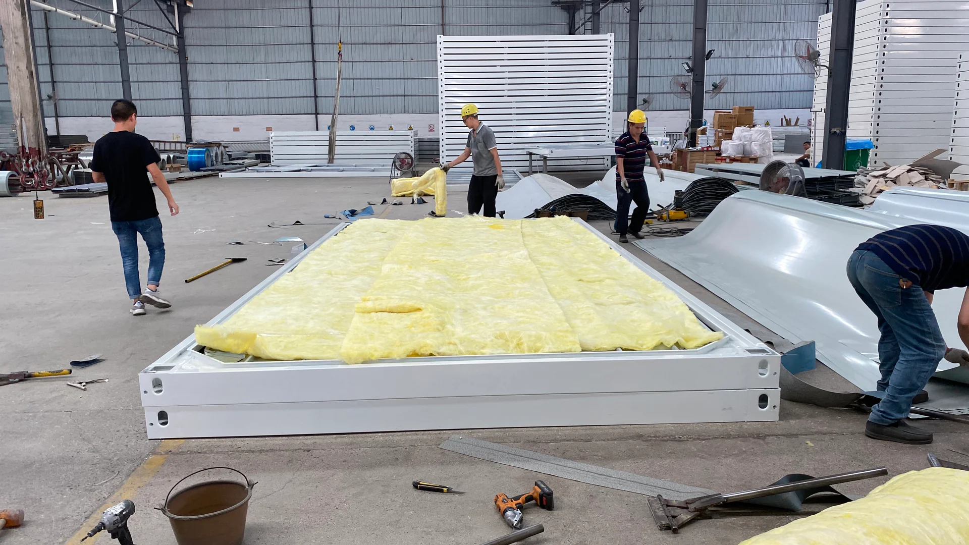
A factory reference view showing workers placing yellow fibrous insulation into a horizontal framed assembly captures an important manufacturing stage: some materials and interfaces remain visible before the outer skin closes them.
The image does not establish insulation density, thermal resistance, fire rating or a passed inspection. It does, however, illustrate why review before covering can be valuable.
Four conditions warrant attention:
Continuity. Insulation should be coordinated around framing, edges and any designed interruptions. Visual presence in the central field does not establish continuity at perimeter members, joints or penetrations.
Dry condition. Fibrous materials and adjacent surfaces should be managed so that the approved assembly is not knowingly closed around unsuitable moisture or contamination. The applicable acceptance condition must come from the project specification and manufacturer requirements.
Service routes. Cables, conduits, pipes, sleeves, outlets and openings may pass through or beside enclosure layers. Their paths should be frozen before closure where later access would require removing skins or finishes.
Later access. Components that may need testing, connection or maintenance should not be unintentionally trapped. A factory-integrated route can reduce site work, but excessive closure may make field joining or troubleshooting harder.
This is one of the central factory-integration trade-offs. More integration can move work into a controlled manufacturing setting, yet every external connection still needs physical access and a defined termination point. Less integration may simplify customization in the field, but it increases dependence on site labor, supervision, weather protection and coordination between trades.
An inspection-before-covering point can be useful when the contract or project quality plan requires it. That point should specify what is being checked—material identity, route, visible condition, placement or photographic record—without assuming that one photograph proves all hidden work.
Factory Preparation and Site Completion Are Different Deliverables
Off-site construction crosses more organizational boundaries than conventional descriptions such as “supply” and “installation” suggest. The ICC off-site and modular committee overview describes the wider process as including planning, design, fabrication, transportation, assembly, in-plant and on-site inspection, MEP and final-site completion. The referenced standards depend on adoption and jurisdiction; the overview does not certify KUBO or determine the requirements of a specific destination.
For a KUBO project, responsibilities need to be allocated among the manufacturer, buyer or EPC, site contractor and locally responsible engineer or authority. The following matrix is a recommended scope-clarification model, not a declaration that every contract assigns work in exactly this way.
| Work or release item | Manufacturer role | Buyer or EPC role | Site contractor role | Local engineer or authority role |
|---|---|---|---|---|
| Approved drawings and material release | Prepare coordinated manufacturer drawings, schedules and proposed materials within the contracted scope; release production after required approvals. | Provide project criteria, consolidate comments, approve commercial and technical selections through the agreed process. | Review buildability, access and installation implications before release where appointed. | Confirm locally regulated design inputs, submissions and acceptance requirements where applicable. |
| Fabricated assemblies | Fabricate the contracted frames, panels and prepared components against released information; perform agreed factory checks. | Monitor submittal and inspection requirements; appoint third-party inspection if contractually required. | Plan unloading, staging and assembly around the approved component form. | Review or witness only where required by the applicable process. |
| Protected loose components | Identify and protect loose panels, trims, fasteners, openings, fittings and other contracted items according to the packing plan. | Confirm spares, packaging, mark conventions and receiving-document requirements. | Maintain package identification, protect items after receipt and report discrepancies. | Normally no packing role, except where regulated materials or procedures require review. |
| Factory-side service provision | Provide the agreed level of openings, internal routes, fixtures, wiring, plumbing or termination points. | Define voltage, frequency, fixture schedule, equipment loads, sanitary requirements and connection boundary. | Complete field joints, external connections and site testing assigned to the installation scope. | Establish local electrical, plumbing, energy or inspection requirements and accept work as applicable. |
| Foundations and anchorage | Provide module reactions, interface information or proposed details when included and supported by project engineering. | Supply site investigation and design criteria; appoint the responsible foundation designer. | Construct foundations, verify setting-out and install anchorage according to approved documents. | Review foundation and anchorage design under local requirements. |
| Structural joining | Supply specified connection components and manufacturer assembly information. | Confirm erection method, temporary works boundary and inspection plan. | Align, connect, brace and complete modules under the approved method. | Review structural completion when required by jurisdiction or project governance. |
| Weather interfaces | Provide factory-installed roof, wall and opening elements plus contracted loose joint materials. | Define performance criteria and assign every factory-to-field interface. | Complete module joints, flashings, penetrations, sealants and drainage connections assigned to site work. | Confirm applicable enclosure, energy and safety requirements. |
| Utility connection and testing | Complete factory tests defined in the contract and provide agreed interface information. | Coordinate utility availability, test criteria and commissioning responsibilities. | Connect external services and perform assigned site tests or commissioning activities. | Inspect, authorize or accept regulated connections where required. |
| Local approval | Support the agreed technical submittal with available drawings and product information. | Own the approval strategy unless the contract explicitly reallocates it; appoint local professionals. | Provide site records and as-installed information within its scope. | Determine local compliance, permitting and acceptance. |
No table can replace the contract’s responsibility schedule. Its value is to expose gaps before they become site variation claims.
The KUBO manufacturing and project-delivery overview describes a process moving from drawing and material release through steel preparation, frame fabrication, enclosure or MEP integration, inspection and protected dispatch. The applicable stages still depend on the selected configuration and contracted scope. A factory capability should not be interpreted as automatic inclusion of every available operation.
Packing Protects Components, Not Just a Box
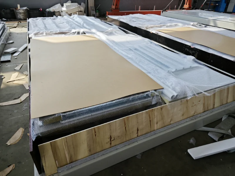
Factory images of flat packages with bubble film, board separators and timber edge protection show surface and edge-protection measures applied to components. These views do not establish a completed loading or cargo-securement design, an approved lifting method, a shipment quantity or the condition that will exist after transport.
Component vulnerability differs across the package:
-
painted or coated frame surfaces can be scratched at contact points;
-
floor finishes can be indented, contaminated or abraded;
-
panel edges and corners can be crushed;
-
long trims can bend or become separated from the module set;
-
windows and glazing require different protection from steel members;
-
seals, fasteners and small fittings can be lost despite representing little package volume;
-
service components may require dry protection and clear circuit or room identification.
Compact packing creates an important commercial trade-off. Reducing unused package volume can support logistics planning, but tighter packs require deliberate layer order, separators, protection and identification. A buyer should be able to relate each package to a module, floor, building block or installation sequence rather than receiving an undifferentiated collection of similar parts.
The receiving handoff is equally important. Factory protection ends when the package is opened or damaged unless a site preservation plan takes over. The site team needs a suitable unloading and staging area, package controls, discrepancy reporting and a way to protect parts that are not installed immediately.
The IMO/ILO/UNECE CTU Code overview identifies the CTU Code as a non-mandatory global code of practice addressing the packing and handling of cargo transport units across sea and land transport. Its relevance here is limited but useful: wrapping and edge protection are only part of cargo preparation. They do not replace an approved loading, weight-distribution, restraint, handling or transport-unit plan.
Detailed shipping-density calculations and last-mile logistics belong in their respective project analyses. At the component level, the procurement questions are narrower: Is the part protected according to its vulnerability? Is it identifiable? Can its condition and completeness be checked at handover?
Connecting Components to Documents
Physical parts become controllable project deliverables when their identities remain connected to approved documents. That connection does not require an excessive paperwork system, but it does require consistent release and receiving logic.
The matrix below is a recommended project framework. It is not a completed KUBO inspection record, and it does not imply that every listed document exists under every quotation or contract.
| Component or interface | Drawing or material release item | Approved-variant control | Package identity | Inspection-before-covering or dispatch | Receiving check |
|---|---|---|---|---|---|
| Floor frame | Frame drawing, member schedule and connection details | Member sections, steel description, finish and connection variant tied to the released module type | Frame or module code linked to building and level | Dimensions, visible fabrication condition, connection locations and finish checks as contractually defined | Package identity, visible damage, distortion and connection-component count |
| Floor build-up | Floor section, board schedule and finish schedule | Board type and thickness, wearing surface, color and room-specific variation | Room or module code; finish rolls or boards linked to the correct set | Support arrangement and hidden-layer checks where specified before finish closure | Surface condition, material match, quantity and protected storage |
| Columns and roof frame | Structural assembly and joint drawings | Column, perimeter-member, secondary-member and reinforcement variants separated | Module and connection-set identification | Alignment, dimensions, connection regions and coating condition under the agreed plan | Member count, marks, visible damage and compatibility with floor-frame set |
| Roof and insulation layers | Roof build-up, drainage detail and penetration schedule | Sheet profile, thickness reference, insulation selection, outlet and flashing variant | Roof set linked to module or building position | Material placement, routes, visible dry condition and designed interfaces before skin closure where required | Sheet and trim condition, outlet parts, seals and penetration accessories |
| Wall and opening assemblies | Elevations, wall-panel schedule, door and window schedule | Panel thickness/core/facing, opening size, handing, hardware, glazing and color | Elevation, room or module position marked on panels and openings | Opening compatibility, hardware, panel condition and factory-installed seals where applicable | Correct handing, dimensions, quantity, glazing condition and panel-edge damage |
| Seals, trims and fasteners | Joint map, trim details and fixing schedule | Profile, material, color, seal type and fastener variant | Bag, bundle or kit tied to joint or module set | Kit completeness and compatibility before dispatch | Count, label, storage condition and issue to the correct installation team |
| Service interfaces | MEP layout, schematic, termination schedule and test boundary | Voltage/frequency, outlet or fixture type, cable or pipe selection and external connection point | Circuit, room, module and service-kit identification | Hidden routes and factory tests only as defined in the inspection plan | Interface location, component condition, documentation and site-test requirements |
A practical release sequence starts with the approved module variant, not with generic catalogue content. The variant drives the drawing set; the drawing set drives the material and component schedule; the schedule drives package identity; package identity enables inspection and receiving checks. If a substitution is proposed, the documentation should show whether it changes only one item or alters connected trims, openings, thermal paths, finishes or service interfaces.
This handoff is particularly important for distributors and EPC contractors managing multiple buildings. Repeated modules can simplify planning, but repeated-looking parts also make misallocation easy. A left-handed door, different wall-panel thickness or service panel for another voltage may look sufficiently similar during rapid unloading to reach the wrong installation area.
Buyer Decisions Hidden Inside the Component List
A detailed component list does not remove design trade-offs. It makes them visible enough to manage.
Standardized bays versus larger openings
Repeated structural bays support common member lengths, panel sizes and package sets. Larger or relocated openings may improve the intended room function but can require revised framing, joint details and unique parts. The commercial decision is not “standard good, custom bad.” It is whether the operational value of the opening justifies its structural, documentation and installation consequences.
Factory integration versus field access
Factory-installed components can reduce exposed site work and support repeatability. Field completion remains preferable where external services, module joints or locally selected equipment require access and adjustment. The boundary should be placed where the responsible team can realistically inspect, connect, test and maintain the work.
Compact packages versus protection and identification
Compactness can help transport planning, while dense packages expose adjacent materials to contact and make installation sequencing more dependent on pack order. Protection, labeling and receiving controls must develop with the packing design—not after the package is already closed.
Material specification versus whole-assembly performance
A thicker panel, different core or named floor board can be commercially meaningful. None should be used as shorthand for complete-building thermal, structural, fire, acoustic or durability performance. Those outcomes depend on the assembled system, interfaces, exposure and applicable assessment method.
Nominal dimensions versus usable and transport dimensions
The external module envelope, internal usable space, fabrication dimensions, packed dimensions, lifting geometry and transport clearances serve different purposes. Procurement teams should request the dimension relevant to each decision rather than circulating one “module size” across architecture, foundations, freight and installation planning.
A complete package versus a complete building scope
A package may contain every contracted KUBO component yet still exclude foundations, local utility infrastructure, field sealants, cranes, temporary works, testing, permits or locally sourced items. Conversely, the supplier may be capable of coordinating certain items without those items being included in the current price or release.
Completeness should therefore be tested against a responsibility matrix and approved schedule, not judged from an exploded image or packing photograph.
What to Resolve Before Component Release
Before approving production, the buyer or EPC team should be able to answer the following questions:
-
Which exact module variant and drawing revision are being released?
-
Which dimensions control the architectural layout, foundations, internal planning, transport and site assembly?
-
Which members form the structural frame, and where is each member’s geometry and connection defined?
-
What loads and project conditions will the responsible engineer use?
-
Which floor board and wearing surface apply to each room type?
-
Which wall-panel variant applies to each elevation or internal partition?
-
Where are the roof’s drainage paths, joints, outlets and penetrations?
-
Which trims, seals and fasteners are factory installed, packed loose or locally supplied?
-
What is the precise factory-side MEP boundary?
-
Which concealed items require inspection or recording before closure?
-
How will packages be marked against buildings, floors, rooms and installation sequence?
-
Who checks the shipment at dispatch, receipt, assembly and utility commissioning?
-
Which items require review or approval from a locally responsible engineer or authority?
KUBO can use project location, application, layout, quantity, customization and delivery information to clarify the relevant module and interface scope. Procurement teams can submit those inputs through the KUBO project contact page before treating catalogue references as released project requirements.
Frequently Asked Questions
1. Are visually similar components from different orders interchangeable?
Do not assume interchangeability from appearance. The buyer or EPC document controller should compare order number, module variant, drawing revision, material schedule, finish, connection detail and package identity before authorizing reassignment. KUBO can help clarify manufacturer-side compatibility within the contracted scope, but the project’s responsible engineer must review any structural or regulated interface. Record the decision so receiving and installation teams do not treat a one-time approval as a general substitution rule.
2. What should happen if a drawing revision is issued after components have been packed?
The buyer or EPC change owner should freeze affected packages until the revision impact is assessed. Compare the new drawing against the released material schedule, fabricated parts, loose kits, labels and site interfaces. KUBO should identify affected manufacturer-supplied items where included in its scope; site and local-design consequences remain with their assigned parties. Repacking, relabeling, modification or replacement should follow a documented disposition rather than an informal site instruction.
3. Does approval of one reference sample authorize mass production?
Not unless the agreed approval process explicitly makes it the production baseline. The buyer’s authorized approver should record what the sample validates—such as appearance, finish, fit or selected hardware—and what remains subject to drawings, specifications or testing. Any differences between the sample and mass-production configuration should be resolved before release. A visual sample cannot independently approve hidden materials, structural details, enclosure performance or service interfaces that it does not demonstrate.
4. What should the receiving team do when a package label does not match the enclosed parts?
Quarantine the affected package without distributing its contents across the site. The receiving lead should photograph the label, protective condition and identifiable parts, then compare them with the packing list, package map and approved component schedule. Report the discrepancy through the project’s designated channel to KUBO and the EPC document controller. Relabeling or reassignment should occur only after identity and destination are confirmed, with the correction preserved in receiving records.
5. Can a locally purchased fastener or seal replace a missing supplied item?
Local availability does not establish equivalence. The party controlling the affected interface should submit the proposed replacement with product identification, dimensions, material, coating or compatibility information and intended location. KUBO can review compatibility with its supplied assembly where contractually applicable, while the responsible engineer or authority addresses regulated performance. Do not approve substitution solely because the item fits physically; its effect on structure, weather control, corrosion or maintenance may differ.
6. Is damaged wrapping acceptable when the protected component shows no visible damage?
Treat damaged protection as a receiving exception, not automatic component rejection or acceptance. The receiving lead should document where protection failed, inspect the exposed area under suitable conditions and identify whether moisture, contamination, abrasion or displaced separators could have affected concealed surfaces. Preserve or restore protection if storage continues. The project quality representative should decide whether further inspection is needed, using the component specification and agreed receiving criteria rather than appearance alone.
7. What evidence should be requested when concealed factory work is no longer visible?
The buyer or EPC quality lead should request evidence appropriate to the specified hold point: released drawings, material identification, production records, dated photographs, relevant factory checks or test results where these were included in the project plan. KUBO should provide documents committed within its scope, but not every configuration automatically carries every record type. If evidence is insufficient, the responsible parties should assess risk and disposition without assuming that closure proves either compliance or nonconformance.
8. How should responsibilities be preserved when the EPC changes its installation subcontractor?
The EPC project manager should formally reissue the approved drawings, scope boundary, installation information, open technical queries, inspection plan and responsibility matrix to the replacement subcontractor. Competence, site access and supervision arrangements should be reassessed before work continues. KUBO’s manufacturer-side obligations do not automatically expand because the site contractor changes. Record the handover and require acknowledgment so unresolved interfaces are not lost between the outgoing and incoming teams.
9. What must be reviewed when the buyer selects different doors or windows?
The buyer’s design coordinator should submit the selected opening product with dimensions, weight, handing, frame depth, fixing requirements, hardware, glazing and relevant performance information. KUBO can evaluate effects on manufacturer-prepared openings, trims and adjacent components within its scope. The responsible engineer should address structural or locally regulated consequences. Approval should cover the complete opening interface—not merely the door leaf or window unit—before affected frames and panels are released.
10. How do factory acceptance, receiving acceptance and permission to occupy differ?
Factory acceptance concerns the contracted manufacturer deliverables before dispatch; receiving acceptance records package identity, quantity and apparent condition at handover; permission to occupy follows completed assembly, utility connection, testing and applicable local approval. The buyer or EPC should assign a decision owner and evidence set for each gate. Acceptance at one stage should not be presented as acceptance of later work, and none should be inferred as a universal regulatory approval from KUBO.
Sources and References
-
KUBO manufacturer reference catalogue, flat-pack component section, pp. 16–19. Used for the illustrated reference dimensions, frame shorthand and identified component or layer examples.
-
KUBO Flat Pack Container House. Public context for system selection, configuration and project-specific engineering boundaries.
-
KUBO About Us and Manufacturing Process. Public manufacturer context covering drawing release, fabrication, integration, inspection and dispatch stages.
-
KUBO Project Contact. Project-information channel for configuration and scope clarification.
-
International Code Council Off-Site and Modular Standard Consensus Committee overview. Public overview of the planning, design, fabrication, transportation, assembly, inspection, MEP and regulatory scope addressed by off-site construction standards.
-
WBDG Building Enclosure Design Principles and Strategies. Building-science guidance on structure, heat, air, moisture and continuity at enclosure interfaces.
-
U.S. Department of Energy Building Energy Codes Program thermal-bridging FAQ. U.S. calculation-framework example distinguishing insulation inputs from whole-assembly thermal performance.
-
IMO/ILO/UNECE CTU Code overview. Overview of the non-mandatory global code of practice for packing and handling cargo transport units by sea and land.